

V
FIGURE 4.19
Optical parametric generation in nonlinear crystals.
Amplification of chirped
pulses was used in radar and
is now used in lasers — this
trend from microwave to
optical range can be taken as
one of the generic principles
of AS-TRIZ.
FIGURE 4.20
Optical parametric chirped pulse amplification — OPCPA.
66 unifying physics of accelerators, lasers and plasma
The schematics of a laser stretcher and compressor are
presented in Section 4.3.4. The stretcher and compressor use
a pair of diffraction gratings and rely on the fact that the angle of reflection from the grating depends on the wavelength,
which sends different colors along different paths. The spectral width of the short laser pulse with duration τ is approximately given by Δf ∼ 1/τ. This finite spread of the spectrum
around the carrier frequency makes such laser pulses suitable
for spatial–spectral manipulation.
The schematics of CPA are shown in Fig. 4.18. The initial short pulse is provided by a short-pulse oscillator. The
first pair of gratings disperses the spectrum and stretches the
pulse by a factor of about a thousand (for visibility, the longitudinal extent of the pulses in Fig. 4.18 is shown qualitatively). After stretching, the pulse is long and has a low peak
power, which is thus safer for amplification. After passing the
power amplifier, the pulse is sent to the second pair of gratings, which reverses the dispersion of the first pair and compresses the pulse, producing a high-energy ultra-short laser
pulse.
The invention of CPA was one of the factors that ultimately pushed laser technology to such peak power levels
that these lasers became a possible competitor alongside particle accelerators.
4.2.6 OPCPA — optical parametric CPA
Another method of laser amplification is called OPCPA —
optical parametric CPA. Its principle is based on nonlinear
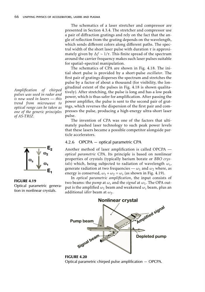
properties of crystals (typically barium borate or BBO crystals) which, being subjected to radiation of wavelength ω s ,
generate radiation at two frequencies — ω 1 and ω 2 where, as
energy is conserved, ω 1 + ω 2 = ω s (as shown in Fig. 4.19).
In optical parametric amplification, the input consists of
two beams: the pump at ω s and the signal at ω 1 . The OPA output is the amplified ω 1 beam and weakened ω s beam, plus an
additional idler beam at ω 2 .
FIGURE 4.19
Optical parametric generation in nonlinear crystals.
Amplification of chirped
pulses was used in radar and
is now used in lasers — this
trend from microwave to
optical range can be taken as
one of the generic principles
of AS-TRIZ.
FIGURE 4.20
Optical parametric chirped pulse amplification — OPCPA.
66 unifying physics of accelerators, lasers and plasma
The schematics of a laser stretcher and compressor are
presented in Section 4.3.4. The stretcher and compressor use
a pair of diffraction gratings and rely on the fact that the angle of reflection from the grating depends on the wavelength,
which sends different colors along different paths. The spectral width of the short laser pulse with duration τ is approximately given by Δf ∼ 1/τ. This finite spread of the spectrum
around the carrier frequency makes such laser pulses suitable
for spatial–spectral manipulation.
The schematics of CPA are shown in Fig. 4.18. The initial short pulse is provided by a short-pulse oscillator. The
first pair of gratings disperses the spectrum and stretches the
pulse by a factor of about a thousand (for visibility, the longitudinal extent of the pulses in Fig. 4.18 is shown qualitatively). After stretching, the pulse is long and has a low peak
power, which is thus safer for amplification. After passing the
power amplifier, the pulse is sent to the second pair of gratings, which reverses the dispersion of the first pair and compresses the pulse, producing a high-energy ultra-short laser
pulse.
The invention of CPA was one of the factors that ultimately pushed laser technology to such peak power levels
that these lasers became a possible competitor alongside particle accelerators.
4.2.6 OPCPA — optical parametric CPA
Another method of laser amplification is called OPCPA —
optical parametric CPA. Its principle is based on nonlinear
properties of crystals (typically barium borate or BBO crystals) which, being subjected to radiation of wavelength ω s ,
generate radiation at two frequencies — ω 1 and ω 2 where, as
energy is conserved, ω 1 + ω 2 = ω s (as shown in Fig. 4.19).
In optical parametric amplification, the input consists of
two beams: the pump at ω s and the signal at ω 1 . The OPA output is the amplified ω 1 beam and weakened ω s beam, plus an
additional idler beam at ω 2 .