

132 unifying physics of accelerators, lasers and plasma
In this section, we will look into a generic layout of such
sources, and will briefly touch on their experimental capabilities.
7.3.1 Layout of a synchrotron radiation source
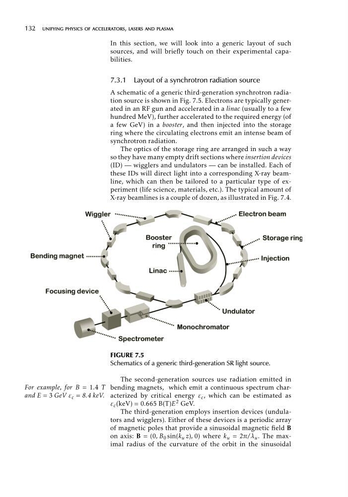
A schematic of a generic third-generation synchrotron radiation source is shown in Fig. 7.5. Electrons are typically generated in an RF gun and accelerated in a linac (usually to a few
hundred MeV), further accelerated to the required energy (of
a few GeV) in a booster, and then injected into the storage
ring where the circulating electrons emit an intense beam of
synchrotron radiation.
The optics of the storage ring are arranged in such a way
so they have many empty drift sections where insertion devices
(ID) — wigglers and undulators — can be installed. Each of
these IDs will direct light into a corresponding X-ray beamline, which can then be tailored to a particular type of experiment (life science, materials, etc.). The typical amount of
X-ray beamlines is a couple of dozen, as illustrated in Fig. 7.4.
FIGURE 7.5
Schematics of a generic third-generation SR light source.
The second-generation sources use radiation emitted in
For example, for B = 1.4 T bending magnets, which emit a continuous spectrum charand E = 3 GeV ε c = 8.4 keV. acterized by critical energy ε c , which can be estimated as
ε c (keV) = 0.665 B(T)E 2 GeV.
The third-generation employs insertion devices (undulators and wigglers). Either of these devices is a periodic array
of magnetic poles that provide a sinusoidal magnetic field B
on axis: B = (0, B 0 sin(k u z), 0) where k u = 2π/λ u . The maximal radius of the curvature of the orbit in the sinusoidal
In this section, we will look into a generic layout of such
sources, and will briefly touch on their experimental capabilities.
7.3.1 Layout of a synchrotron radiation source
A schematic of a generic third-generation synchrotron radiation source is shown in Fig. 7.5. Electrons are typically generated in an RF gun and accelerated in a linac (usually to a few
hundred MeV), further accelerated to the required energy (of
a few GeV) in a booster, and then injected into the storage
ring where the circulating electrons emit an intense beam of
synchrotron radiation.
The optics of the storage ring are arranged in such a way
so they have many empty drift sections where insertion devices
(ID) — wigglers and undulators — can be installed. Each of
these IDs will direct light into a corresponding X-ray beamline, which can then be tailored to a particular type of experiment (life science, materials, etc.). The typical amount of
X-ray beamlines is a couple of dozen, as illustrated in Fig. 7.4.
FIGURE 7.5
Schematics of a generic third-generation SR light source.
The second-generation sources use radiation emitted in
For example, for B = 1.4 T bending magnets, which emit a continuous spectrum charand E = 3 GeV ε c = 8.4 keV. acterized by critical energy ε c , which can be estimated as
ε c (keV) = 0.665 B(T)E 2 GeV.
The third-generation employs insertion devices (undulators and wigglers). Either of these devices is a periodic array
of magnetic poles that provide a sinusoidal magnetic field B
on axis: B = (0, B 0 sin(k u z), 0) where k u = 2π/λ u . The maximal radius of the curvature of the orbit in the sinusoidal