

conventional acceleration 101
5.5.6 Accelerator technologies and applications
Table 5.1 shows typical accelerating gradients for RF cavities
of various frequencies for linear accelerators.
TABLE 5.1
Operating frequencies and typical parameters for RF cavities
Warm cavities
Gradient
Repetition rate
S-band (3GHz)
C-band (5-6 GHz)
X-band (12 GHz)
15-25 MV/m
30-40 MV/m
100 MV/m
50-300 Hz
<100 Hz
<100 Hz
Superconducting cavities Gradient
Repetition rate
L-band (1.3 GHz)
< 35 MV/m up to CW
As we can see, the achievable gradient generally increases
with frequency, consistent with frequency dependences of
Eq.5.25 and Eq.5.26 (these relationships, however, haven’t yet
been demonstrated for frequencies higher than 12 GHz).
The practically achievable gradient is one of the main factors that define the size of accelerator-based facilities of various kinds. Let’s consider a couple of examples.
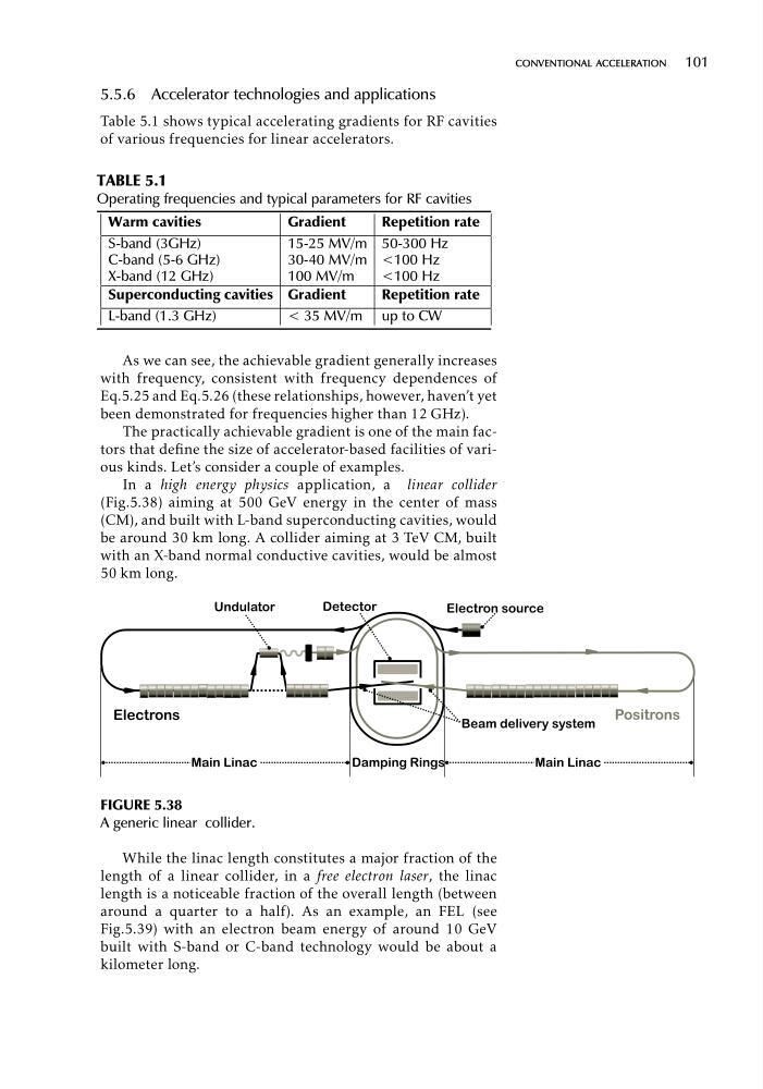
In a high energy physics application, a linear collider
(Fig.5.38) aiming at 500 GeV energy in the center of mass
(CM), and built with L-band superconducting cavities, would
be around 30 km long. A collider aiming at 3 TeV CM, built
with an X-band normal conductive cavities, would be almost
50 km long.
FIGURE 5.38
A generic linear collider.
While the linac length constitutes a major fraction of the
length of a linear collider, in a free electron laser, the linac
length is a noticeable fraction of the overall length (between
around a quarter to a half). As an example, an FEL (see
Fig.5.39) with an electron beam energy of around 10 GeV
built with S-band or C-band technology would be about a
kilometer long.
5.5.6 Accelerator technologies and applications
Table 5.1 shows typical accelerating gradients for RF cavities
of various frequencies for linear accelerators.
TABLE 5.1
Operating frequencies and typical parameters for RF cavities
Warm cavities
Gradient
Repetition rate
S-band (3GHz)
C-band (5-6 GHz)
X-band (12 GHz)
15-25 MV/m
30-40 MV/m
100 MV/m
50-300 Hz
<100 Hz
<100 Hz
Superconducting cavities Gradient
Repetition rate
L-band (1.3 GHz)
< 35 MV/m up to CW
As we can see, the achievable gradient generally increases
with frequency, consistent with frequency dependences of
Eq.5.25 and Eq.5.26 (these relationships, however, haven’t yet
been demonstrated for frequencies higher than 12 GHz).
The practically achievable gradient is one of the main factors that define the size of accelerator-based facilities of various kinds. Let’s consider a couple of examples.
In a high energy physics application, a linear collider
(Fig.5.38) aiming at 500 GeV energy in the center of mass
(CM), and built with L-band superconducting cavities, would
be around 30 km long. A collider aiming at 3 TeV CM, built
with an X-band normal conductive cavities, would be almost
50 km long.
FIGURE 5.38
A generic linear collider.
While the linac length constitutes a major fraction of the
length of a linear collider, in a free electron laser, the linac
length is a noticeable fraction of the overall length (between
around a quarter to a half). As an example, an FEL (see
Fig.5.39) with an electron beam energy of around 10 GeV
built with S-band or C-band technology would be about a
kilometer long.