

Synchrotron Motion
257
π
π
π
π
Δ((
φUDG
π
π
π
π
φUDG
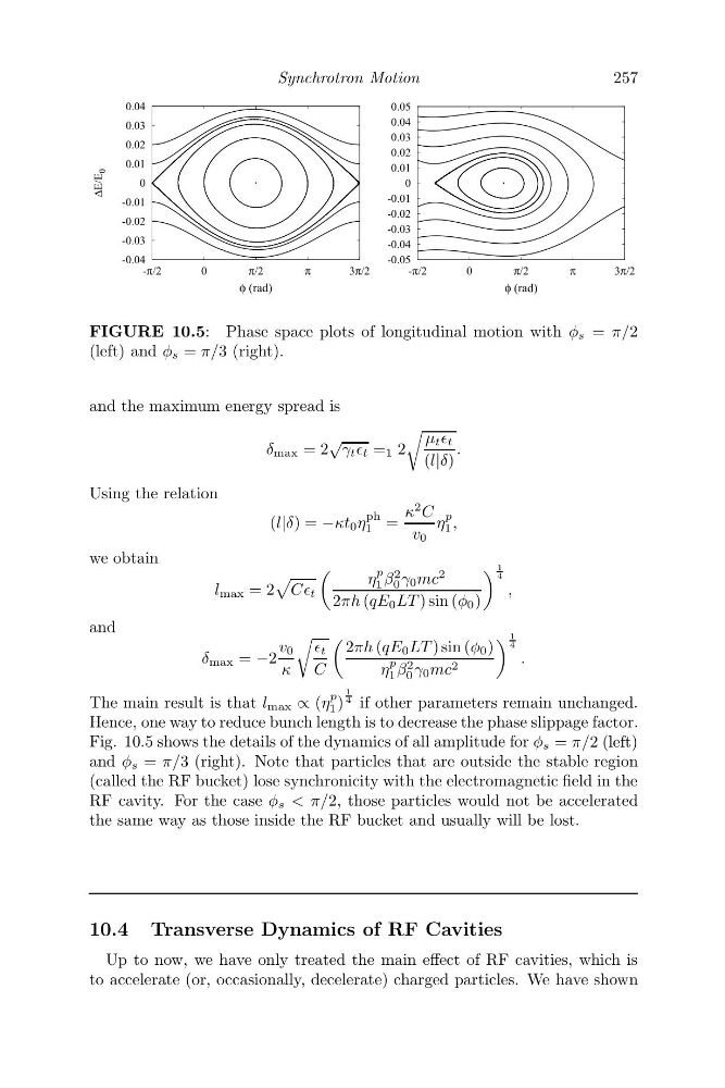
FIGURE 10.5: Phase space plots of longitudinal motion with φ s = π/2
(left) and φ s = π/3 (right).
and the maximum energy spread is
δ max = 2
√
γ t t = 1 2
μ t t
(l|δ)
.
Using the relation
(l|δ) = −κt 0 η
ph
1 =
κ
2 C
v 0
η
p
1 ,
we obtain
l max = 2
CC t
η
p
1 β
2
0 γ 0 mc
2
2πh (qE 0 LT ) sin (φ 0 )
1
4
,
and
δ max = −2
v 0
κ
t
C
2πh (qE 0 LT ) sin (φ 0 )
η
p
1 β 2
0 γ 0 mc 2
1
4
.
The main result is that l max ∝ (η
p
1 )
1
4 if other parameters remain unchanged.
Hence, one way to reduce bunch length is to decrease the phase slippage factor.
Fig. 10.5 shows the details of the dynamics of all amplitude for φ s = π/2 (left)
and φ s = π/3 (right). Note that particles that are outside the stable region
(called the RF bucket) lose synchronicity with the electromagnetic field in the
RF cavity. For the case φ s < π/2, those particles would not be accelerated
the same way as those inside the RF bucket and usually will be lost.
10.4 Transverse Dynamics of RF Cavities
Up to now, we have only treated the main effect of RF cavities, which is
to accelerate (or, occasionally, decelerate) charged particles. We have shown
257
π
π
π
π
Δ((
φUDG
π
π
π
π
φUDG
FIGURE 10.5: Phase space plots of longitudinal motion with φ s = π/2
(left) and φ s = π/3 (right).
and the maximum energy spread is
δ max = 2
√
γ t t = 1 2
μ t t
(l|δ)
.
Using the relation
(l|δ) = −κt 0 η
ph
1 =
κ
2 C
v 0
η
p
1 ,
we obtain
l max = 2
CC t
η
p
1 β
2
0 γ 0 mc
2
2πh (qE 0 LT ) sin (φ 0 )
1
4
,
and
δ max = −2
v 0
κ
t
C
2πh (qE 0 LT ) sin (φ 0 )
η
p
1 β 2
0 γ 0 mc 2
1
4
.
The main result is that l max ∝ (η
p
1 )
1
4 if other parameters remain unchanged.
Hence, one way to reduce bunch length is to decrease the phase slippage factor.
Fig. 10.5 shows the details of the dynamics of all amplitude for φ s = π/2 (left)
and φ s = π/3 (right). Note that particles that are outside the stable region
(called the RF bucket) lose synchronicity with the electromagnetic field in the
RF cavity. For the case φ s < π/2, those particles would not be accelerated
the same way as those inside the RF bucket and usually will be lost.
10.4 Transverse Dynamics of RF Cavities
Up to now, we have only treated the main effect of RF cavities, which is
to accelerate (or, occasionally, decelerate) charged particles. We have shown