

94
An Introduction to Beam Physics
and at s = S,
V 0 (S) = −SE 0 , K(S) = K 0 + ZeSE 0 ,
p s (S) = p S =
2m (K 0 + ZeSE 0 ).
Thus, we obtain the transfer matrices at s = 0 and s = S as
ˆ
M 0 =
1 0
α 1
,
ˆ
M S =
1
0
−α(p 0 /p S ) 1
,
(4.15)
where again the abbreviation
α = −
E 0
2χ e0
is used.
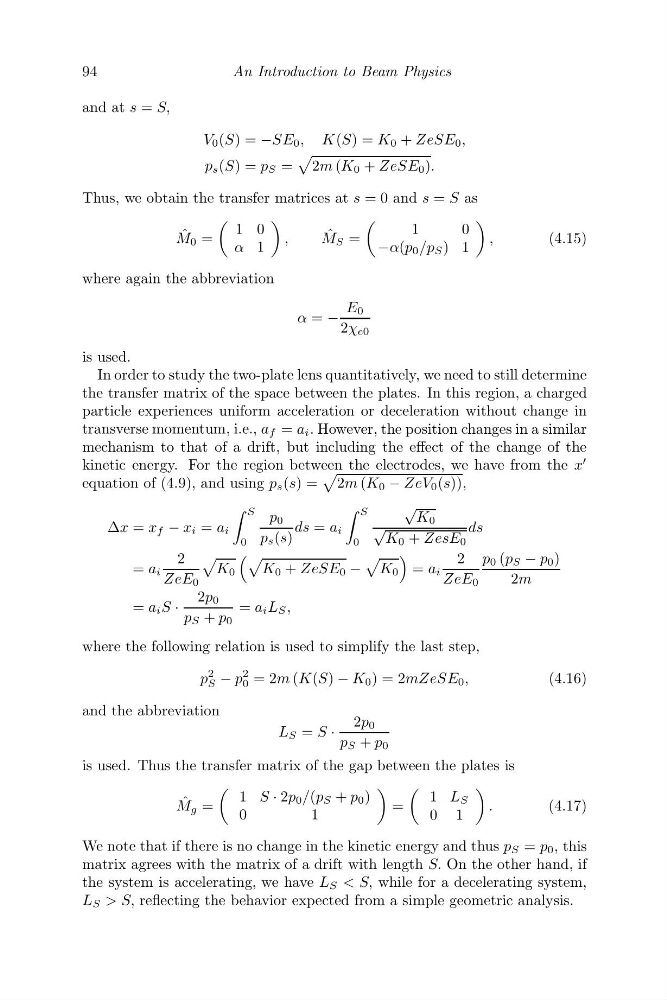
In order to study the two-plate lens quantitatively, we need to still determine
the transfer matrix of the space between the plates. In this region, a charged
particle experiences uniform acceleration or deceleration without change in
transverse momentum, i.e., a f = a i . However, the position changes in a similar
mechanism to that of a drift, but including the effect of the change of the
kinetic energy. For the region between the electrodes, we have from the x
equation of (4.9), and using p s (s) =
2m (K 0 − ZeV 0 (s)),
Δx = x f − x i = a i
S
0
p 0
p s (s)
ds = a i
S
0
√
K 0
√
K 0 + ZesE 0
ds
= a i
2
ZeE 0
K 0
K 0 + ZeSE 0 −
K 0
= a i
2
ZeE 0
p 0 (p S − p 0 )
2m
= a i S ·
2p 0
p S + p 0
= a i L S ,
where the following relation is used to simplify the last step,
p
2
S − p
2
0 = 2m (K(S) − K 0 ) = 2mZeSE 0 ,
(4.16)
and the abbreviation
L S = S ·
2p 0
p S + p 0
is used. Thus the transfer matrix of the gap between the plates is
ˆ
M g =
1 S · 2p 0 /(p S + p 0 )
0
1
=
1 L S
0 1
.
(4.17)
We note that if there is no change in the kinetic energy and thus p S = p 0 , this
matrix agrees with the matrix of a drift with length S. On the other hand, if
the system is accelerating, we have L S < S, while for a decelerating system,
L S > S, reflecting the behavior expected from a simple geometric analysis.
An Introduction to Beam Physics
and at s = S,
V 0 (S) = −SE 0 , K(S) = K 0 + ZeSE 0 ,
p s (S) = p S =
2m (K 0 + ZeSE 0 ).
Thus, we obtain the transfer matrices at s = 0 and s = S as
ˆ
M 0 =
1 0
α 1
,
ˆ
M S =
1
0
−α(p 0 /p S ) 1
,
(4.15)
where again the abbreviation
α = −
E 0
2χ e0
is used.
In order to study the two-plate lens quantitatively, we need to still determine
the transfer matrix of the space between the plates. In this region, a charged
particle experiences uniform acceleration or deceleration without change in
transverse momentum, i.e., a f = a i . However, the position changes in a similar
mechanism to that of a drift, but including the effect of the change of the
kinetic energy. For the region between the electrodes, we have from the x
equation of (4.9), and using p s (s) =
2m (K 0 − ZeV 0 (s)),
Δx = x f − x i = a i
S
0
p 0
p s (s)
ds = a i
S
0
√
K 0
√
K 0 + ZesE 0
ds
= a i
2
ZeE 0
K 0
K 0 + ZeSE 0 −
K 0
= a i
2
ZeE 0
p 0 (p S − p 0 )
2m
= a i S ·
2p 0
p S + p 0
= a i L S ,
where the following relation is used to simplify the last step,
p
2
S − p
2
0 = 2m (K(S) − K 0 ) = 2mZeSE 0 ,
(4.16)
and the abbreviation
L S = S ·
2p 0
p S + p 0
is used. Thus the transfer matrix of the gap between the plates is
ˆ
M g =
1 S · 2p 0 /(p S + p 0 )
0
1
=
1 L S
0 1
.
(4.17)
We note that if there is no change in the kinetic energy and thus p S = p 0 , this
matrix agrees with the matrix of a drift with length S. On the other hand, if
the system is accelerating, we have L S < S, while for a decelerating system,
L S > S, reflecting the behavior expected from a simple geometric analysis.