

� �
� �
� �
� �
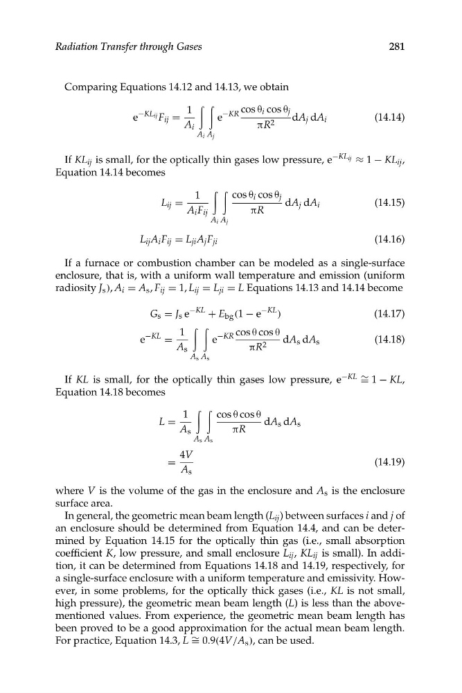
Comparing Equations 14.12 and 14.13, we obtain
e
−KL ij F ij =
1
A i
e
−KR cos θ i cos θ j
πR 2
dA j dA i
(14.14)
A i A j
If KL ij is small, for the optically thin gases low pressure, e
−KL ij ≈ 1 − KL ij ,
Equation 14.14 becomes
1
cos θ i cos θ j dA j dA i
(14.15)
πR
L ij = A i F ij
A i A j
(14.16)
L ij A i F ij = L ji A j F ji
If a furnace or combustion chamber can be modeled as a single-surface
enclosure, that is, with a uniform wall temperature and emission (uniform
radiosity J s ), A i = A s , F ij = 1, L ij = L ji = L Equations 14.13 and 14.14 become
−KL
G s = J s e
−KL
+ E bg (1 − e
)
(14.17)
1
e
−KR cos θ cos θ
πR 2
dA s dA s
(14.18)
−KL
e
= A s
A s A s
If KL is small, for the optically thin gases low pressure, e −KL ∼ = 1 − KL,
Equation 14.18 becomes
L =
1
A s
cos θ cos θ dA s dA s
πR
A s A s
4V
=
(14.19)
A s
281
Radiation Transfer through Gases
where V is the volume of the gas in the enclosure and A s is the enclosure
surface area.
In general, the geometric mean beam length (L ij ) between surfaces i and j of
an enclosure should be determined from Equation 14.4, and can be determined by Equation 14.15 for the optically thin gas (i.e., small absorption
coefficient K, low pressure, and small enclosure L ij , KL ij is small). In addition, it can be determined from Equations 14.18 and 14.19, respectively, for
a single-surface enclosure with a uniform temperature and emissivity. However, in some problems, for the optically thick gases (i.e., KL is not small,
high pressure), the geometric mean beam length (L) is less than the abovementioned values. From experience, the geometric mean beam length has
been proved to be a good approximation for the actual mean beam length.
For practice, Equation 14.3, L ∼ = 0.9(4V/A s ), can be used.
� �
� �
� �
Comparing Equations 14.12 and 14.13, we obtain
e
−KL ij F ij =
1
A i
e
−KR cos θ i cos θ j
πR 2
dA j dA i
(14.14)
A i A j
If KL ij is small, for the optically thin gases low pressure, e
−KL ij ≈ 1 − KL ij ,
Equation 14.14 becomes
1
cos θ i cos θ j dA j dA i
(14.15)
πR
L ij = A i F ij
A i A j
(14.16)
L ij A i F ij = L ji A j F ji
If a furnace or combustion chamber can be modeled as a single-surface
enclosure, that is, with a uniform wall temperature and emission (uniform
radiosity J s ), A i = A s , F ij = 1, L ij = L ji = L Equations 14.13 and 14.14 become
−KL
G s = J s e
−KL
+ E bg (1 − e
)
(14.17)
1
e
−KR cos θ cos θ
πR 2
dA s dA s
(14.18)
−KL
e
= A s
A s A s
If KL is small, for the optically thin gases low pressure, e −KL ∼ = 1 − KL,
Equation 14.18 becomes
L =
1
A s
cos θ cos θ dA s dA s
πR
A s A s
4V
=
(14.19)
A s
281
Radiation Transfer through Gases
where V is the volume of the gas in the enclosure and A s is the enclosure
surface area.
In general, the geometric mean beam length (L ij ) between surfaces i and j of
an enclosure should be determined from Equation 14.4, and can be determined by Equation 14.15 for the optically thin gas (i.e., small absorption
coefficient K, low pressure, and small enclosure L ij , KL ij is small). In addition, it can be determined from Equations 14.18 and 14.19, respectively, for
a single-surface enclosure with a uniform temperature and emissivity. However, in some problems, for the optically thick gases (i.e., KL is not small,
high pressure), the geometric mean beam length (L) is less than the abovementioned values. From experience, the geometric mean beam length has
been proved to be a good approximation for the actual mean beam length.
For practice, Equation 14.3, L ∼ = 0.9(4V/A s ), can be used.