

Inside
hot fluid
l
T s,1
T s,2
r 2
r 1
Outside
cold fluid
T ∞,2 h 2
T ∞,1 h 1
T ∞,1
T s,1
T s,2
T ∞,2
q
q
1
ln(r 2 /r 1 )
1
h 1 2πr 1 l
2πkl
h 2 2πr 2 l
16
Analytical Heat Transfer
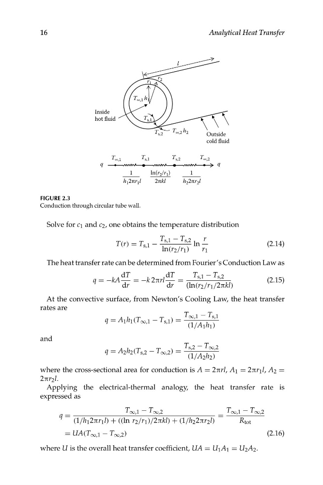
FIGURE 2.3
Conduction through circular tube wall.
Solve for c 1 and c 2 , one obtains the temperature distribution
T s,1 − T s,2
r
T(r) = T s,1 −
ln
(2.14)
ln(r 2 /r 1 )
r 1
The heat transfer rate can be determined from Fourier’s Conduction Law as
dT
dT
T s,1 − T s,2
q = −kA
= −k 2πrl
=
(2.15)
dr
dr
(ln (r 2 /r 1 /2πkl)
At the convective surface, from Newton’s Cooling Law, the heat transfer
rates are
T ∞,1 − T s,1
q = A 1 h 1 (T ∞,1 − T s,1 ) =
(1/A 1 h 1 )
and
T s,2 − T ∞,2
q = A 2 h 2 (T s,2 − T ∞,2 ) =
(1/A 2 h 2 )
where the cross-sectional area for conduction is A = 2πrl, A 1 = 2πr 1 l, A 2 =
2πr 2 l.
Applying the electrical-thermal analogy, the heat transfer rate is
expressed as
T ∞,1 − T ∞,2
T ∞,1 − T ∞,2
q =
=
(1/h 1 2πr 1 l) + ((ln r 2 /r 1 )/2πkl) + (1/h 2 2πr 2 l)
R tot
= UA(T ∞,1 − T ∞,2 )
(2.16)
where U is the overall heat transfer coefficient, UA = U 1 A 1 = U 2 A 2 .
hot fluid
l
T s,1
T s,2
r 2
r 1
Outside
cold fluid
T ∞,2 h 2
T ∞,1 h 1
T ∞,1
T s,1
T s,2
T ∞,2
q
q
1
ln(r 2 /r 1 )
1
h 1 2πr 1 l
2πkl
h 2 2πr 2 l
16
Analytical Heat Transfer
FIGURE 2.3
Conduction through circular tube wall.
Solve for c 1 and c 2 , one obtains the temperature distribution
T s,1 − T s,2
r
T(r) = T s,1 −
ln
(2.14)
ln(r 2 /r 1 )
r 1
The heat transfer rate can be determined from Fourier’s Conduction Law as
dT
dT
T s,1 − T s,2
q = −kA
= −k 2πrl
=
(2.15)
dr
dr
(ln (r 2 /r 1 /2πkl)
At the convective surface, from Newton’s Cooling Law, the heat transfer
rates are
T ∞,1 − T s,1
q = A 1 h 1 (T ∞,1 − T s,1 ) =
(1/A 1 h 1 )
and
T s,2 − T ∞,2
q = A 2 h 2 (T s,2 − T ∞,2 ) =
(1/A 2 h 2 )
where the cross-sectional area for conduction is A = 2πrl, A 1 = 2πr 1 l, A 2 =
2πr 2 l.
Applying the electrical-thermal analogy, the heat transfer rate is
expressed as
T ∞,1 − T ∞,2
T ∞,1 − T ∞,2
q =
=
(1/h 1 2πr 1 l) + ((ln r 2 /r 1 )/2πkl) + (1/h 2 2πr 2 l)
R tot
= UA(T ∞,1 − T ∞,2 )
(2.16)
where U is the overall heat transfer coefficient, UA = U 1 A 1 = U 2 A 2 .