

10
2
Varactor
10 2
10
1
multipliers
10
1
Power (mW)
JPL
10
0
10
−1
RTD
GaAs TUNNETT
frequency
multipliers
10
0
10
−1
10
−2
Varistor
10 −2
10
−3
multipliers
10
−3
10
−4
10
−4
10
−5
0.1
1
10 −5
Frequency (THz)
10 3
InP Gunn
10 3
Si IMPATT
381
Terahertz Radiation
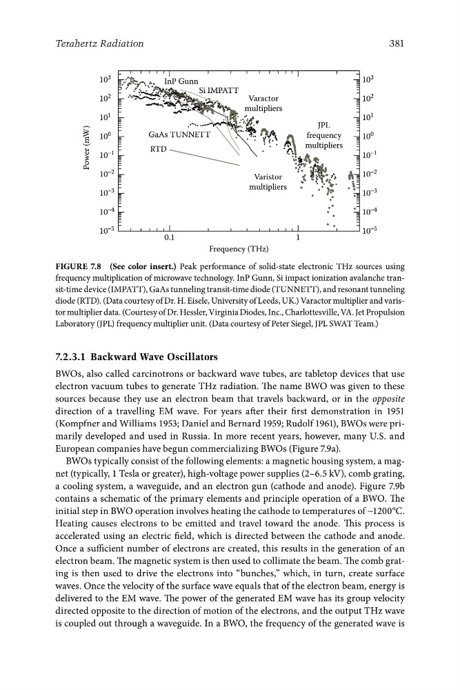
Figure 7.8 (See color insert.) Peak performance of solid-state electronic THz sources using
frequency multiplication of microwave technology. InP Gunn, Si impact ionization avalanche transit-time device (IMPATT), GaAs tunneling transit-time diode (TUNNETT), and resonant tunneling
diode (RTD). (Data courtesy of Dr. H. Eisele, University of Leeds, UK.) Varactor multiplier and varistor multiplier data. (Courtesy of Dr. Hessler, Virginia Diodes, Inc., Charlottesville, VA. Jet Propulsion
Laboratory (JPL) frequency multiplier unit. (Data courtesy of Peter Siegel, JPL SWAT Team.)
7.2.3.1 Backward Wave Oscillators
BWOs, also called carcinotrons or backward wave tubes, are tabletop devices that use
electron vacuum tubes to generate THz radiation. The name BWO was given to these
sources because they use an electron beam that travels backward, or in the opposite
direction of a travelling EM wave. For years after their first demonstration in 1951
(Kompfner and Williams 1953; Daniel and Bernard 1959; Rudolf 1961), BWOs were primarily developed and used in Russia. In more recent years, however, many U.S. and
European companies have begun commercializing BWOs (Figure 7.9a).
BWOs typically consist of the following elements: a magnetic housing system, a magnet (typically, 1 Tesla or greater), high-voltage power supplies (2–6.5 kV), comb grating,
a cooling system, a waveguide, and an electron gun (cathode and anode). Figure 7.9b
contains a schematic of the primary elements and principle operation of a BWO. The
initial step in BWO operation involves heating the cathode to temperatures of ∼1200°C.
Heating causes electrons to be emitted and travel toward the anode. This process is
accelerated using an electric field, which is directed between the cathode and anode.
Once a sufficient number of electrons are created, this results in the generation of an
electron beam. The magnetic system is then used to collimate the beam. The comb grating is then used to drive the electrons into “bunches,” which, in turn, create surface
waves. Once the velocity of the surface wave equals that of the electron beam, energy is
delivered to the EM wave. The power of the generated EM wave has its group velocity
directed opposite to the direction of motion of the electrons, and the output THz wave
is coupled out through a waveguide. In a BWO, the frequency of the generated wave is
2
Varactor
10 2
10
1
multipliers
10
1
Power (mW)
JPL
10
0
10
−1
RTD
GaAs TUNNETT
frequency
multipliers
10
0
10
−1
10
−2
Varistor
10 −2
10
−3
multipliers
10
−3
10
−4
10
−4
10
−5
0.1
1
10 −5
Frequency (THz)
10 3
InP Gunn
10 3
Si IMPATT
381
Terahertz Radiation
Figure 7.8 (See color insert.) Peak performance of solid-state electronic THz sources using
frequency multiplication of microwave technology. InP Gunn, Si impact ionization avalanche transit-time device (IMPATT), GaAs tunneling transit-time diode (TUNNETT), and resonant tunneling
diode (RTD). (Data courtesy of Dr. H. Eisele, University of Leeds, UK.) Varactor multiplier and varistor multiplier data. (Courtesy of Dr. Hessler, Virginia Diodes, Inc., Charlottesville, VA. Jet Propulsion
Laboratory (JPL) frequency multiplier unit. (Data courtesy of Peter Siegel, JPL SWAT Team.)
7.2.3.1 Backward Wave Oscillators
BWOs, also called carcinotrons or backward wave tubes, are tabletop devices that use
electron vacuum tubes to generate THz radiation. The name BWO was given to these
sources because they use an electron beam that travels backward, or in the opposite
direction of a travelling EM wave. For years after their first demonstration in 1951
(Kompfner and Williams 1953; Daniel and Bernard 1959; Rudolf 1961), BWOs were primarily developed and used in Russia. In more recent years, however, many U.S. and
European companies have begun commercializing BWOs (Figure 7.9a).
BWOs typically consist of the following elements: a magnetic housing system, a magnet (typically, 1 Tesla or greater), high-voltage power supplies (2–6.5 kV), comb grating,
a cooling system, a waveguide, and an electron gun (cathode and anode). Figure 7.9b
contains a schematic of the primary elements and principle operation of a BWO. The
initial step in BWO operation involves heating the cathode to temperatures of ∼1200°C.
Heating causes electrons to be emitted and travel toward the anode. This process is
accelerated using an electric field, which is directed between the cathode and anode.
Once a sufficient number of electrons are created, this results in the generation of an
electron beam. The magnetic system is then used to collimate the beam. The comb grating is then used to drive the electrons into “bunches,” which, in turn, create surface
waves. Once the velocity of the surface wave equals that of the electron beam, energy is
delivered to the EM wave. The power of the generated EM wave has its group velocity
directed opposite to the direction of motion of the electrons, and the output THz wave
is coupled out through a waveguide. In a BWO, the frequency of the generated wave is