

THz-QCLs
FIR gas laser
p-Ge laser
Power (mW)
10
−2
10
−1
10
0
10
1
10
2
10
3
10
4
10
5
10
−2
10
−1
10
0
10
1
10
2
10
3
10
4
10
5
0.1
1
10
Frequency (THz)
(a) InP Gunn (0.48 THz)
Frequency multiplier (1.9 THz) Frequency multiplier (2.7 THz)
(b) Frequency multiplication of microwaves (up-conversion)
Microwave oscillator: Gunn diode
Frequency multiplier element
Input waveguide
Input antenna
Output antenna
Output waveguide
THz emission
ω in
3ω in = ω out
R
R R
C
L
+ −
379
Terahertz Radiation
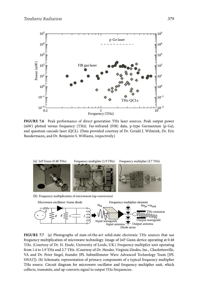
Figure 7.6 Peak performance of direct generation THz laser sources. Peak output power
(mW) plotted versus frequency (THz). Far-infrared (FIR) data, p-type Germanium (p-Ge),
and quantum cascade laser (QCL). (Data provided courtesy of Dr. Gerald J. Wilmink, Dr. Eric
Bundermann, and Dr. Benjamin S. Williams, respectively.)
Diode array
Figure 7.7 (a) Photographs of state-of-the-art solid-state electronic THz sources that use
frequency multiplication of microwave technology. Image of InP Gunn device operating at 0.48
THz. (Courtesy of Dr. H. Eisele, University of Leeds, UK.) Frequency multiplier unit operating
from 1.4 to 1.9 THz and 2.7 THz. (Courtesy of Dr. Hessler, Virginia Diodes, Inc., Charlottesville,
VA and Dr. Peter Siegel, founder JPL Submillimeter Wave Advanced Technology Team [JPL
SWAT]). (b) Schematic representation of primary components of a typical frequency multiplier
THz source. Circuit diagram for microwave oscillator and frequency multiplier unit, which
collects, transmits, and up-converts signal to output THz frequencies.
FIR gas laser
p-Ge laser
Power (mW)
10
−2
10
−1
10
0
10
1
10
2
10
3
10
4
10
5
10
−2
10
−1
10
0
10
1
10
2
10
3
10
4
10
5
0.1
1
10
Frequency (THz)
(a) InP Gunn (0.48 THz)
Frequency multiplier (1.9 THz) Frequency multiplier (2.7 THz)
(b) Frequency multiplication of microwaves (up-conversion)
Microwave oscillator: Gunn diode
Frequency multiplier element
Input waveguide
Input antenna
Output antenna
Output waveguide
THz emission
ω in
3ω in = ω out
R
R R
C
L
+ −
379
Terahertz Radiation
Figure 7.6 Peak performance of direct generation THz laser sources. Peak output power
(mW) plotted versus frequency (THz). Far-infrared (FIR) data, p-type Germanium (p-Ge),
and quantum cascade laser (QCL). (Data provided courtesy of Dr. Gerald J. Wilmink, Dr. Eric
Bundermann, and Dr. Benjamin S. Williams, respectively.)
Diode array
Figure 7.7 (a) Photographs of state-of-the-art solid-state electronic THz sources that use
frequency multiplication of microwave technology. Image of InP Gunn device operating at 0.48
THz. (Courtesy of Dr. H. Eisele, University of Leeds, UK.) Frequency multiplier unit operating
from 1.4 to 1.9 THz and 2.7 THz. (Courtesy of Dr. Hessler, Virginia Diodes, Inc., Charlottesville,
VA and Dr. Peter Siegel, founder JPL Submillimeter Wave Advanced Technology Team [JPL
SWAT]). (b) Schematic representation of primary components of a typical frequency multiplier
THz source. Circuit diagram for microwave oscillator and frequency multiplier unit, which
collects, transmits, and up-converts signal to output THz frequencies.