

203
Interaction of Extremely Low–Frequency Electromagnetic Fields
problems are the quasistatic finite-difference time domain (FDTD) method (Dawson
and Stuchly 1996; Hirata et al. 2001; Gustrau et al. 1999), the finite-element method
(FEM) (Baraton and Hutlzer 1995), the charge simulation method (CSM) (Yamazaki
et al. 2000b), and the surface charge method (Hamada and Kobayashi 2006a; Yamazaki
et al. 2000c).
4.3.1 Impedance Method
The IM solves circuit network equations involving a human hosting impedance networks (Orcutt and Gandhi 1988). This method is illustrated in the following example
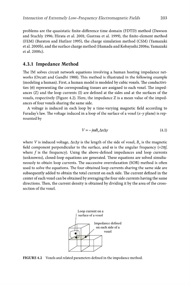
(modeling a human). First, a human model is modeled by cubic voxels. The conductivities (σ) representing the corresponding tissues are assigned to each voxel. The impedances (Z) and the loop currents (I) are defined at the sides and at the surfaces of the
voxels, respectively (Figure 4.2). Here, the impedance Z is a mean value of the impedances of four voxels sharing the same side.
A voltage is induced in each loop by a time-varying magnetic field according to
Faraday’s law. The voltage induced in a loop of the surface of a voxel (x–y plane) is represented by
V = − ω Δ Δ
j B x y
(4.1)
n
where V is induced voltage, ΔxΔy is the length of the side of voxel, B n is the magnetic
field component perpendicular to the surface, and ω is the angular frequency (=2πf,
where f is the frequency). Using the above-defined impedances and loop currents
(unknowns), closed-loop equations are generated. These equations are solved simultaneously to obtain loop currents. The successive overrelaxation (SOR) method is often
used to solve the equations. The four obtained loop currents sharing the same side are
subsequently added to obtain the total current on each side. The current defined in the
center of each voxel can be obtained by averaging the four side currents having the same
directions. Then, the current density is obtained by dividing it by the area of the crosssection of the voxel.
surface of a voxel
Loop current on a
Impedance defined
on each side of a
voxel
Figure 4.2 Voxels and related parameters defined in the impedance method.