

212
13 Tunnel Flow and Erosion Processes …
Path
Inlet
Outlet
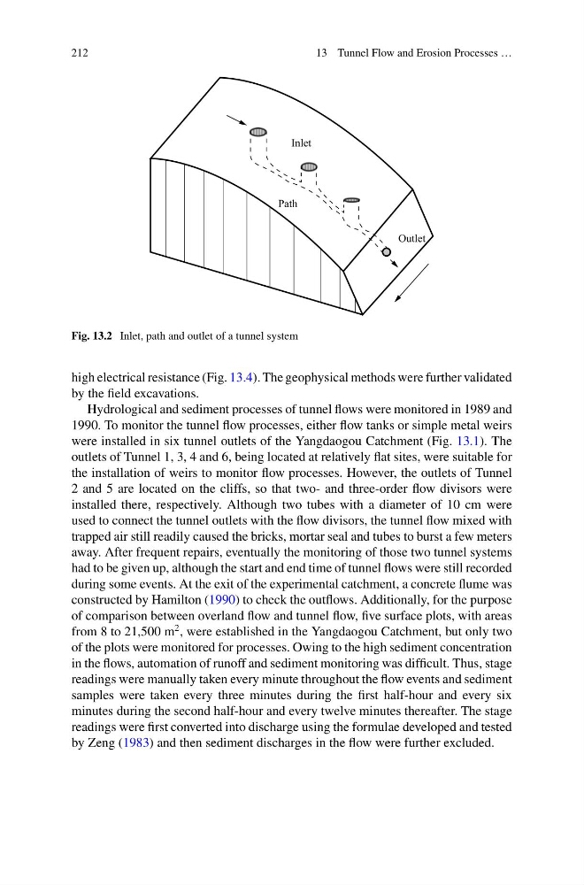
Fig. 13.2 Inlet, path and outlet of a tunnel system
high electrical resistance (Fig. 13.4). The geophysical methods were further validated
by the field excavations.
Hydrological and sediment processes of tunnel flows were monitored in 1989 and
1990. To monitor the tunnel flow processes, either flow tanks or simple metal weirs
were installed in six tunnel outlets of the Yangdaogou Catchment (Fig. 13.1). The
outlets of Tunnel 1, 3, 4 and 6, being located at relatively flat sites, were suitable for
the installation of weirs to monitor flow processes. However, the outlets of Tunnel
2 and 5 are located on the cliffs, so that two- and three-order flow divisors were
installed there, respectively. Although two tubes with a diameter of 10 cm were
used to connect the tunnel outlets with the flow divisors, the tunnel flow mixed with
trapped air still readily caused the bricks, mortar seal and tubes to burst a few meters
away. After frequent repairs, eventually the monitoring of those two tunnel systems
had to be given up, although the start and end time of tunnel flows were still recorded
during some events. At the exit of the experimental catchment, a concrete flume was
constructed by Hamilton (1990) to check the outflows. Additionally, for the purpose
of comparison between overland flow and tunnel flow, five surface plots, with areas
from 8 to 21,500 m
2 , were established in the Yangdaogou Catchment, but only two
of the plots were monitored for processes. Owing to the high sediment concentration
in the flows, automation of runoff and sediment monitoring was difficult. Thus, stage
readings were manually taken every minute throughout the flow events and sediment
samples were taken every three minutes during the first half-hour and every six
minutes during the second half-hour and every twelve minutes thereafter. The stage
readings were first converted into discharge using the formulae developed and tested
by Zeng (1983) and then sediment discharges in the flow were further excluded.
13 Tunnel Flow and Erosion Processes …
Path
Inlet
Outlet
Fig. 13.2 Inlet, path and outlet of a tunnel system
high electrical resistance (Fig. 13.4). The geophysical methods were further validated
by the field excavations.
Hydrological and sediment processes of tunnel flows were monitored in 1989 and
1990. To monitor the tunnel flow processes, either flow tanks or simple metal weirs
were installed in six tunnel outlets of the Yangdaogou Catchment (Fig. 13.1). The
outlets of Tunnel 1, 3, 4 and 6, being located at relatively flat sites, were suitable for
the installation of weirs to monitor flow processes. However, the outlets of Tunnel
2 and 5 are located on the cliffs, so that two- and three-order flow divisors were
installed there, respectively. Although two tubes with a diameter of 10 cm were
used to connect the tunnel outlets with the flow divisors, the tunnel flow mixed with
trapped air still readily caused the bricks, mortar seal and tubes to burst a few meters
away. After frequent repairs, eventually the monitoring of those two tunnel systems
had to be given up, although the start and end time of tunnel flows were still recorded
during some events. At the exit of the experimental catchment, a concrete flume was
constructed by Hamilton (1990) to check the outflows. Additionally, for the purpose
of comparison between overland flow and tunnel flow, five surface plots, with areas
from 8 to 21,500 m
2 , were established in the Yangdaogou Catchment, but only two
of the plots were monitored for processes. Owing to the high sediment concentration
in the flows, automation of runoff and sediment monitoring was difficult. Thus, stage
readings were manually taken every minute throughout the flow events and sediment
samples were taken every three minutes during the first half-hour and every six
minutes during the second half-hour and every twelve minutes thereafter. The stage
readings were first converted into discharge using the formulae developed and tested
by Zeng (1983) and then sediment discharges in the flow were further excluded.