

13.3 Field Study Methods
211
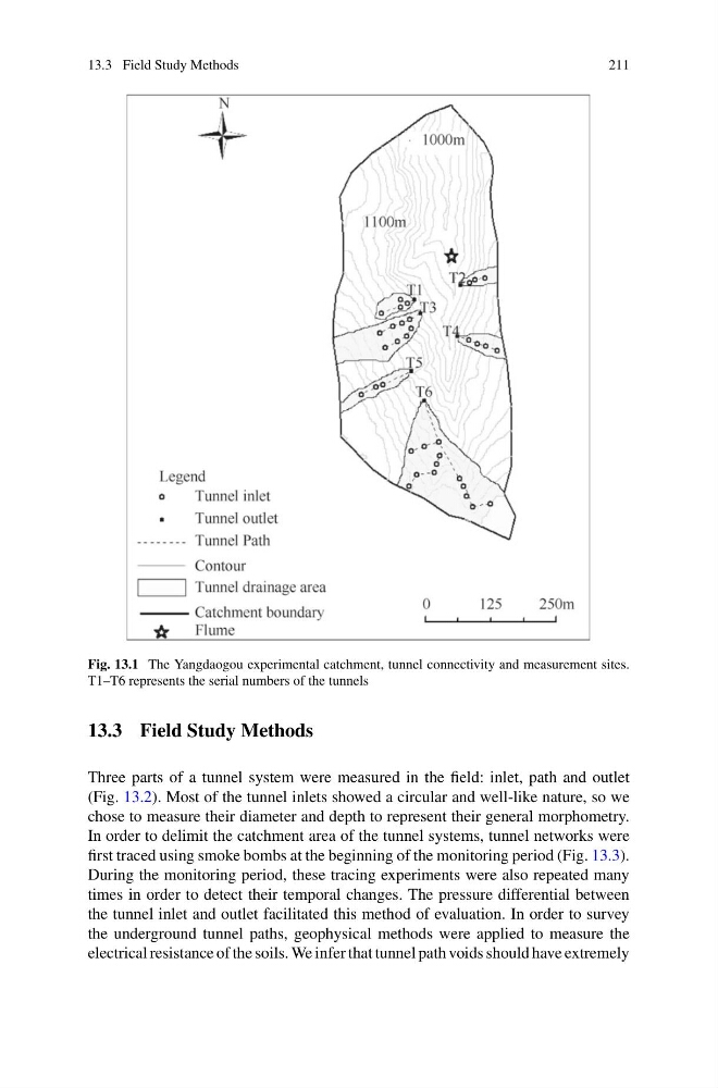
Fig. 13.1 The Yangdaogou experimental catchment, tunnel connectivity and measurement sites.
T1–T6 represents the serial numbers of the tunnels
13.3 Field Study Methods
Three parts of a tunnel system were measured in the field: inlet, path and outlet
(Fig. 13.2). Most of the tunnel inlets showed a circular and well-like nature, so we
chose to measure their diameter and depth to represent their general morphometry.
In order to delimit the catchment area of the tunnel systems, tunnel networks were
first traced using smoke bombs at the beginning of the monitoring period (Fig. 13.3).
During the monitoring period, these tracing experiments were also repeated many
times in order to detect their temporal changes. The pressure differential between
the tunnel inlet and outlet facilitated this method of evaluation. In order to survey
the underground tunnel paths, geophysical methods were applied to measure the
electrical resistance of the soils. We infer that tunnel path voids should have extremely
211
Fig. 13.1 The Yangdaogou experimental catchment, tunnel connectivity and measurement sites.
T1–T6 represents the serial numbers of the tunnels
13.3 Field Study Methods
Three parts of a tunnel system were measured in the field: inlet, path and outlet
(Fig. 13.2). Most of the tunnel inlets showed a circular and well-like nature, so we
chose to measure their diameter and depth to represent their general morphometry.
In order to delimit the catchment area of the tunnel systems, tunnel networks were
first traced using smoke bombs at the beginning of the monitoring period (Fig. 13.3).
During the monitoring period, these tracing experiments were also repeated many
times in order to detect their temporal changes. The pressure differential between
the tunnel inlet and outlet facilitated this method of evaluation. In order to survey
the underground tunnel paths, geophysical methods were applied to measure the
electrical resistance of the soils. We infer that tunnel path voids should have extremely