

Developments in Textile Continuous Processing Machineries
373
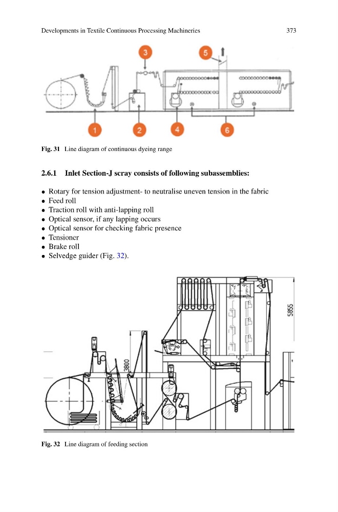
Fig. 31 Line diagram of continuous dyeing range
2.6.1 Inlet Section-J scray consists of following subassemblies:
• Rotary for tension adjustment- to neutralise uneven tension in the fabric
• Feed roll
• Traction roll with anti-lapping roll
• Optical sensor, if any lapping occurs
• Optical sensor for checking fabric presence
• Tensioner
• Brake roll
• Selvedge guider (Fig. 32).
Fig. 32 Line diagram of feeding section
373
Fig. 31 Line diagram of continuous dyeing range
2.6.1 Inlet Section-J scray consists of following subassemblies:
• Rotary for tension adjustment- to neutralise uneven tension in the fabric
• Feed roll
• Traction roll with anti-lapping roll
• Optical sensor, if any lapping occurs
• Optical sensor for checking fabric presence
• Tensioner
• Brake roll
• Selvedge guider (Fig. 32).
Fig. 32 Line diagram of feeding section