

118
6 Particulate Silica Reinforcement of Rubber
6.2.3 Soft Processing from Latex Toward Network Structure
of In Situ Silica
Introduction of in situ silica into rubber using latex was reported by Yoshikai et al.
[70, 71]. Both NR and SBR latexes are stabilized under a basic condition for storage, which is competent for conducting the sol–gel reaction at place. Under this
background, Tohsan et al. successfully prepared silica network structure in the NR
nanocomposite from NR latex [58]. The in situ silica was synthesized selectively
around the interface of rubber particles in NR latex, and a network structure of
in situ silica particles was formed to result in an excellent reinforcing nanofiller in
spite of relatively lower amount of silica (10 phr). In other words, the rubber particles
in the latex are effectively functioning as a template of the in situ silica networks. The
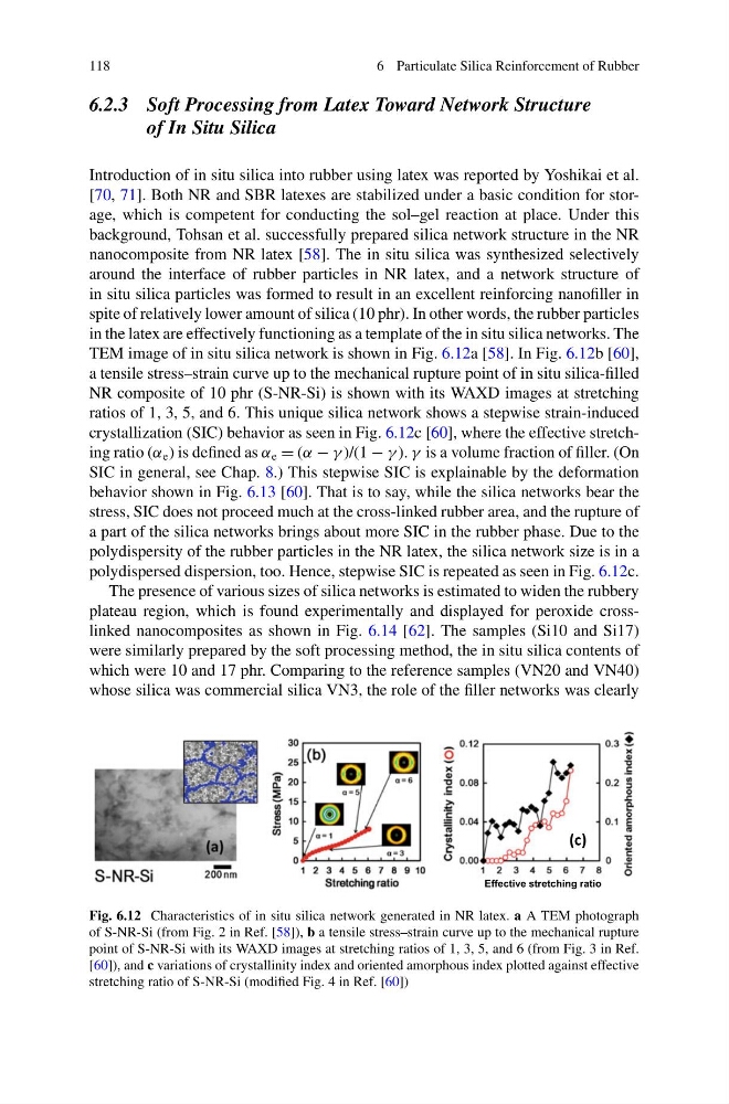
TEM image of in situ silica network is shown in Fig. 6.12a [58]. In Fig. 6.12b [60],
a tensile stress–strain curve up to the mechanical rupture point of in situ silica-filled
NR composite of 10 phr (S-NR-Si) is shown with its WAXD images at stretching
ratios of 1, 3, 5, and 6. This unique silica network shows a stepwise strain-induced
crystallization (SIC) behavior as seen in Fig. 6.12c [60], where the effective stretching ratio (α e ) is defined as α e = (α − γ )/(1 − γ ). γ is a volume fraction of filler. (On
SIC in general, see Chap. 8.) This stepwise SIC is explainable by the deformation
behavior shown in Fig. 6.13 [60]. That is to say, while the silica networks bear the
stress, SIC does not proceed much at the cross-linked rubber area, and the rupture of
a part of the silica networks brings about more SIC in the rubber phase. Due to the
polydispersity of the rubber particles in the NR latex, the silica network size is in a
polydispersed dispersion, too. Hence, stepwise SIC is repeated as seen in Fig. 6.12c.
The presence of various sizes of silica networks is estimated to widen the rubbery
plateau region, which is found experimentally and displayed for peroxide crosslinked nanocomposites as shown in Fig. 6.14 [62]. The samples (Si10 and Si17)
were similarly prepared by the soft processing method, the in situ silica contents of
which were 10 and 17 phr. Comparing to the reference samples (VN20 and VN40)
whose silica was commercial silica VN3, the role of the filler networks was clearly
(c)
Effective stretching ratio
Fig. 6.12 Characteristics of in situ silica network generated in NR latex. a A TEM photograph
of S-NR-Si (from Fig. 2 in Ref. [58]), b a tensile stress–strain curve up to the mechanical rupture
point of S-NR-Si with its WAXD images at stretching ratios of 1, 3, 5, and 6 (from Fig. 3 in Ref.
[60]), and c variations of crystallinity index and oriented amorphous index plotted against effective
stretching ratio of S-NR-Si (modified Fig. 4 in Ref. [60])
6 Particulate Silica Reinforcement of Rubber
6.2.3 Soft Processing from Latex Toward Network Structure
of In Situ Silica
Introduction of in situ silica into rubber using latex was reported by Yoshikai et al.
[70, 71]. Both NR and SBR latexes are stabilized under a basic condition for storage, which is competent for conducting the sol–gel reaction at place. Under this
background, Tohsan et al. successfully prepared silica network structure in the NR
nanocomposite from NR latex [58]. The in situ silica was synthesized selectively
around the interface of rubber particles in NR latex, and a network structure of
in situ silica particles was formed to result in an excellent reinforcing nanofiller in
spite of relatively lower amount of silica (10 phr). In other words, the rubber particles
in the latex are effectively functioning as a template of the in situ silica networks. The
TEM image of in situ silica network is shown in Fig. 6.12a [58]. In Fig. 6.12b [60],
a tensile stress–strain curve up to the mechanical rupture point of in situ silica-filled
NR composite of 10 phr (S-NR-Si) is shown with its WAXD images at stretching
ratios of 1, 3, 5, and 6. This unique silica network shows a stepwise strain-induced
crystallization (SIC) behavior as seen in Fig. 6.12c [60], where the effective stretching ratio (α e ) is defined as α e = (α − γ )/(1 − γ ). γ is a volume fraction of filler. (On
SIC in general, see Chap. 8.) This stepwise SIC is explainable by the deformation
behavior shown in Fig. 6.13 [60]. That is to say, while the silica networks bear the
stress, SIC does not proceed much at the cross-linked rubber area, and the rupture of
a part of the silica networks brings about more SIC in the rubber phase. Due to the
polydispersity of the rubber particles in the NR latex, the silica network size is in a
polydispersed dispersion, too. Hence, stepwise SIC is repeated as seen in Fig. 6.12c.
The presence of various sizes of silica networks is estimated to widen the rubbery
plateau region, which is found experimentally and displayed for peroxide crosslinked nanocomposites as shown in Fig. 6.14 [62]. The samples (Si10 and Si17)
were similarly prepared by the soft processing method, the in situ silica contents of
which were 10 and 17 phr. Comparing to the reference samples (VN20 and VN40)
whose silica was commercial silica VN3, the role of the filler networks was clearly
(c)
Effective stretching ratio
Fig. 6.12 Characteristics of in situ silica network generated in NR latex. a A TEM photograph
of S-NR-Si (from Fig. 2 in Ref. [58]), b a tensile stress–strain curve up to the mechanical rupture
point of S-NR-Si with its WAXD images at stretching ratios of 1, 3, 5, and 6 (from Fig. 3 in Ref.
[60]), and c variations of crystallinity index and oriented amorphous index plotted against effective
stretching ratio of S-NR-Si (modified Fig. 4 in Ref. [60])