

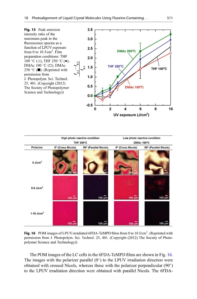
The POM images of the LC cells in the 6FDA-TeMPD films are shown in Fig. 16.
The images with the polarizer parallel (0
) to the LPUV irradiation direction were
obtained with crossed Nicols, whereas those with the polarizer perpendicular (90
)
to the LPUV irradiation direction were obtained with parallel Nicols. The 6FDAFig. 16 POM images of LPUV-irradiated 6FDA-TeMPD films from 0 to 10 J/cm
2
. (Reprinted with
permission from J. Photopolym. Sci. Technol. 25, 401. (Copyright (2012) The Society of Photopolymer Science and Technology))
Fig. 15 Peak emission
intensity ratio of the
maximum peak in the
fluorescence spectra as a
function of LPUV exposure
from 0 to 10 J/cm
2
. Film
preparation conditions: THF
100
C (○), THF 250
C (●),
DMAc 100
C (□), DMAc
250
C (■). (Reprinted with
permission from
J. Photopolym. Sci. Technol.
25, 401. (Copyright (2012)
The Society of Photopolymer
Science and Technology))
18 Photoalignment of Liquid Crystal Molecules Using Fluorine-Containing. . .
511
The images with the polarizer parallel (0
) to the LPUV irradiation direction were
obtained with crossed Nicols, whereas those with the polarizer perpendicular (90
)
to the LPUV irradiation direction were obtained with parallel Nicols. The 6FDAFig. 16 POM images of LPUV-irradiated 6FDA-TeMPD films from 0 to 10 J/cm
2
. (Reprinted with
permission from J. Photopolym. Sci. Technol. 25, 401. (Copyright (2012) The Society of Photopolymer Science and Technology))
Fig. 15 Peak emission
intensity ratio of the
maximum peak in the
fluorescence spectra as a
function of LPUV exposure
from 0 to 10 J/cm
2
. Film
preparation conditions: THF
100
C (○), THF 250
C (●),
DMAc 100
C (□), DMAc
250
C (■). (Reprinted with
permission from
J. Photopolym. Sci. Technol.
25, 401. (Copyright (2012)
The Society of Photopolymer
Science and Technology))
18 Photoalignment of Liquid Crystal Molecules Using Fluorine-Containing. . .
511