

ä
Fig. 21 (continued) inverse opal film (e) before and (f) after UV light irradiation. The red
regular hexagon and straight lines represent the arrangement of the holes before UV light irradiation; the green hexagon and lines represent the arrangement of the holes after irradiation with UV
light. After UV light irradiation, the shape of the hexagon becomes irregular, and the straight lines
have become curves. (g) Reflection spectra of the azobenzene CLCP inverse opal film under UV
light irradiation (365 nm, 50 mW cm
2
, 5 min) and subsequent visible light irradiation (530 nm,
20 mW cm
2
, 15 min). (h) Reflection spectra of the inverse opal film as a function of temperature
(Zhao et al. 2014)
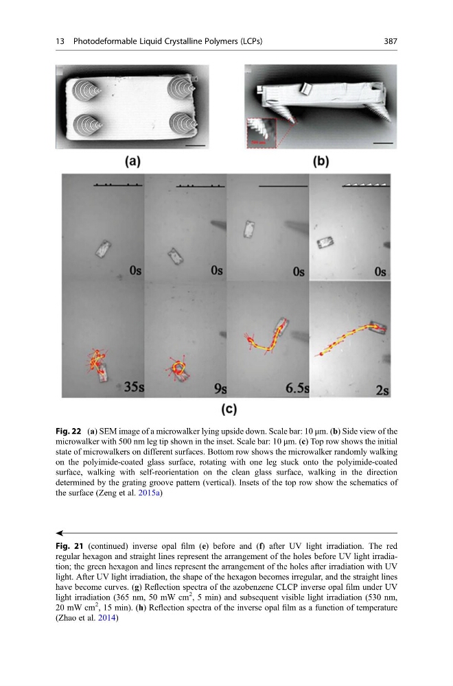
Fig. 22 (a) SEM image of a microwalker lying upside down. Scale bar: 10 μm. (b) Side view of the
microwalker with 500 nm leg tip shown in the inset. Scale bar: 10 μm. (c) Top row shows the initial
state of microwalkers on different surfaces. Bottom row shows the microwalker randomly walking
on the polyimide-coated glass surface, rotating with one leg stuck onto the polyimide-coated
surface, walking with self-reorientation on the clean glass surface, walking in the direction
determined by the grating groove pattern (vertical). Insets of the top row show the schematics of
the surface (Zeng et al. 2015a)
13 Photodeformable Liquid Crystalline Polymers (LCPs)
387
Fig. 21 (continued) inverse opal film (e) before and (f) after UV light irradiation. The red
regular hexagon and straight lines represent the arrangement of the holes before UV light irradiation; the green hexagon and lines represent the arrangement of the holes after irradiation with UV
light. After UV light irradiation, the shape of the hexagon becomes irregular, and the straight lines
have become curves. (g) Reflection spectra of the azobenzene CLCP inverse opal film under UV
light irradiation (365 nm, 50 mW cm
2
, 5 min) and subsequent visible light irradiation (530 nm,
20 mW cm
2
, 15 min). (h) Reflection spectra of the inverse opal film as a function of temperature
(Zhao et al. 2014)
Fig. 22 (a) SEM image of a microwalker lying upside down. Scale bar: 10 μm. (b) Side view of the
microwalker with 500 nm leg tip shown in the inset. Scale bar: 10 μm. (c) Top row shows the initial
state of microwalkers on different surfaces. Bottom row shows the microwalker randomly walking
on the polyimide-coated glass surface, rotating with one leg stuck onto the polyimide-coated
surface, walking with self-reorientation on the clean glass surface, walking in the direction
determined by the grating groove pattern (vertical). Insets of the top row show the schematics of
the surface (Zeng et al. 2015a)
13 Photodeformable Liquid Crystalline Polymers (LCPs)
387