

72
3
Y
e e
ij
i
i j
j i
=
= +
2ε
(3.26)
where
5 e ij = Displacement vector
(In an alternate notation, the strain tensor can be expressed as a
9 × 1 vector in which the first three elements are normal strains and
the remaining six are shear strains. The 9 × 1 tensorial strain vector
can be further simplified as an engineering 6 × 1 vector in which the
shear strain terms are double that of the corresponding tensorial
shear strains. Physically, engineering strain at a point in a plane is
defined as the change in angle between two orthogonal lines at that
point in that plane.)
The mechanical properties of elastic solids within the elastic
limit are defined by Hook’s law, which expresses the linear relationship between σ and ε as
ε
σ
ij
ijkl kl
S
=
(3.27)
σ
ε
ij
ijkl kl
C
=
(3.28)
where S ijkl and C ijkl are compliance and stiffness tensors, respectively, and
ε
ε ε ε
ij
xx
yy
zz
=
…
, , , , .
etc
(3.29)
σ
σ σ σ
kl
xx
yy
zz
=
…
,
, , , .
etc
(3.30)
The i, j, k, and l of S and C are assigned values 1, 2, and 3, and this
becomes synonymous to x, y, and z, respectively. In general, 1, 2,
and 3 and x, y, and z represent local and global coordinates, respectively. It is more convenient to work with a compliance constant
rather than with a stiffness constant due to the ease in experimental
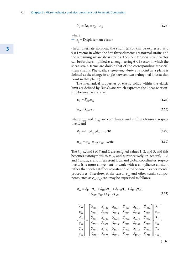
procedures. Therefore, strain tensor ε xx and other strain components, such as ε yy , γ xy , etc., may be expressed as follows:
ε
σ
σ
σ
σ
σ
σ
xx
xx
yy
zz
XZ
YZ
XY
S
S
S
S
S
=
+
+
+
+
+
1111
1122
1133
1113
1123
1112
S
(3.31)
ε
ε
ε
γ
γ
γ
xx
yy
zz
yz
zx
xy
S
S
S
S
=
1111
1122
1133
11 123
1131
1112
2211
2222
2233
2223
2231
2212
3311
3322
333
S
S
S
S
S
S
S
S
S
S
S 3 3
3323
3331
3312
2311
2322
2333
2323
2331
2312
3111
3122
S
S
S
S
S
S
S
S
S
S
S
S 3 3133
3123
3131
3112
1211
1222
1233
1223
1231
1212
S
S
S
S
S
S
S
S
S
σ
σ
σ
τ
τ
τ
xx
yy
zz
yz
zx
xy
(3.32)
Chapter 3 · Micromechanics and Macromechanics of Polymeric Composites
3
Y
e e
ij
i
i j
j i
=
= +
2ε
(3.26)
where
5 e ij = Displacement vector
(In an alternate notation, the strain tensor can be expressed as a
9 × 1 vector in which the first three elements are normal strains and
the remaining six are shear strains. The 9 × 1 tensorial strain vector
can be further simplified as an engineering 6 × 1 vector in which the
shear strain terms are double that of the corresponding tensorial
shear strains. Physically, engineering strain at a point in a plane is
defined as the change in angle between two orthogonal lines at that
point in that plane.)
The mechanical properties of elastic solids within the elastic
limit are defined by Hook’s law, which expresses the linear relationship between σ and ε as
ε
σ
ij
ijkl kl
S
=
(3.27)
σ
ε
ij
ijkl kl
C
=
(3.28)
where S ijkl and C ijkl are compliance and stiffness tensors, respectively, and
ε
ε ε ε
ij
xx
yy
zz
=
…
, , , , .
etc
(3.29)
σ
σ σ σ
kl
xx
yy
zz
=
…
,
, , , .
etc
(3.30)
The i, j, k, and l of S and C are assigned values 1, 2, and 3, and this
becomes synonymous to x, y, and z, respectively. In general, 1, 2,
and 3 and x, y, and z represent local and global coordinates, respectively. It is more convenient to work with a compliance constant
rather than with a stiffness constant due to the ease in experimental
procedures. Therefore, strain tensor ε xx and other strain components, such as ε yy , γ xy , etc., may be expressed as follows:
ε
σ
σ
σ
σ
σ
σ
xx
xx
yy
zz
XZ
YZ
XY
S
S
S
S
S
=
+
+
+
+
+
1111
1122
1133
1113
1123
1112
S
(3.31)
ε
ε
ε
γ
γ
γ
xx
yy
zz
yz
zx
xy
S
S
S
S
=
1111
1122
1133
11 123
1131
1112
2211
2222
2233
2223
2231
2212
3311
3322
333
S
S
S
S
S
S
S
S
S
S
S 3 3
3323
3331
3312
2311
2322
2333
2323
2331
2312
3111
3122
S
S
S
S
S
S
S
S
S
S
S
S 3 3133
3123
3131
3112
1211
1222
1233
1223
1231
1212
S
S
S
S
S
S
S
S
S
σ
σ
σ
τ
τ
τ
xx
yy
zz
yz
zx
xy
(3.32)
Chapter 3 · Micromechanics and Macromechanics of Polymeric Composites