

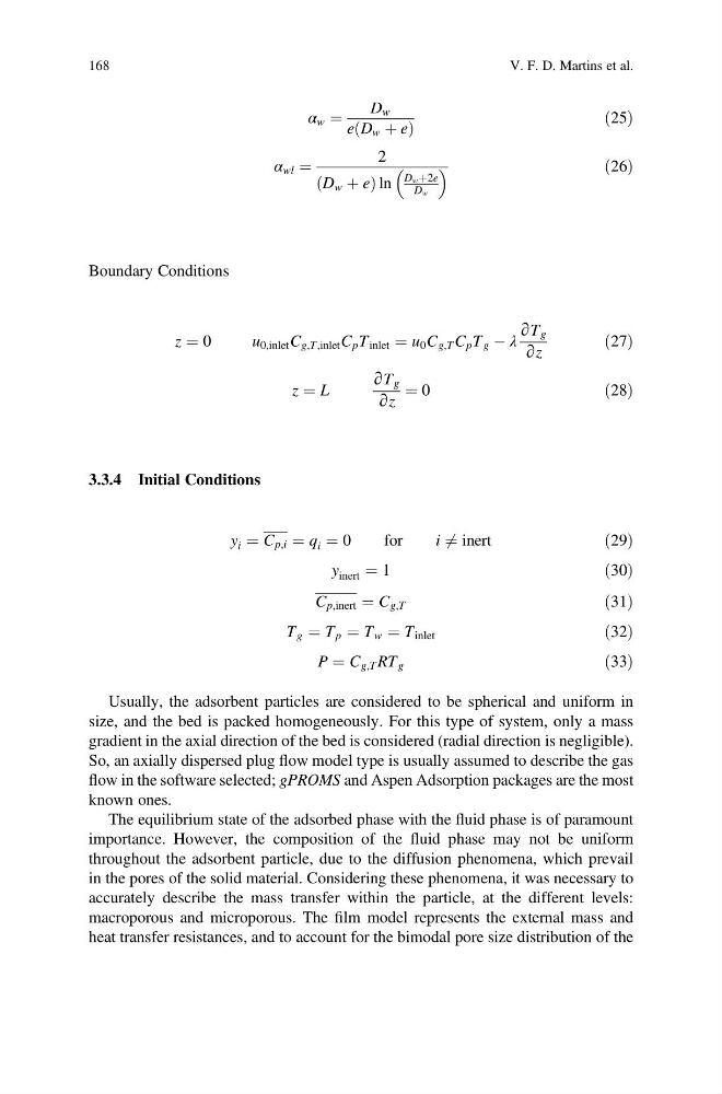
α w ¼
D w
e D w þ e
ð
Þ
ð25Þ
α wl ¼
2
D w þ e
ð
Þln
D w þ2e
D w
ð26Þ
Boundary Conditions
z ¼ 0
u 0,inlet C g,T,inlet C p T inlet ¼ u 0 C g,T C p T g À λ
∂T g
∂z
ð27Þ
z ¼ L
∂T g
∂z
¼ 0
ð28Þ
3.3.4 Initial Conditions
y i ¼ C p,i ¼ q i ¼ 0
for
i 6 ¼ inert
ð29Þ
y inert ¼ 1
ð30Þ
C p,inert ¼ C g,T
ð31Þ
T g ¼ T p ¼ T w ¼ T inlet
ð32Þ
P ¼ C g,T RT g
ð33Þ
Usually, the adsorbent particles are considered to be spherical and uniform in
size, and the bed is packed homogeneously. For this type of system, only a mass
gradient in the axial direction of the bed is considered (radial direction is negligible).
So, an axially dispersed plug flow model type is usually assumed to describe the gas
flow in the software selected; gPROMS and Aspen Adsorption packages are the most
known ones.
The equilibrium state of the adsorbed phase with the fluid phase is of paramount
importance. However, the composition of the fluid phase may not be uniform
throughout the adsorbent particle, due to the diffusion phenomena, which prevail
in the pores of the solid material. Considering these phenomena, it was necessary to
accurately describe the mass transfer within the particle, at the different levels:
macroporous and microporous. The film model represents the external mass and
heat transfer resistances, and to account for the bimodal pore size distribution of the
168
V. F. D. Martins et al.
D w
e D w þ e
ð
Þ
ð25Þ
α wl ¼
2
D w þ e
ð
Þln
D w þ2e
D w
ð26Þ
Boundary Conditions
z ¼ 0
u 0,inlet C g,T,inlet C p T inlet ¼ u 0 C g,T C p T g À λ
∂T g
∂z
ð27Þ
z ¼ L
∂T g
∂z
¼ 0
ð28Þ
3.3.4 Initial Conditions
y i ¼ C p,i ¼ q i ¼ 0
for
i 6 ¼ inert
ð29Þ
y inert ¼ 1
ð30Þ
C p,inert ¼ C g,T
ð31Þ
T g ¼ T p ¼ T w ¼ T inlet
ð32Þ
P ¼ C g,T RT g
ð33Þ
Usually, the adsorbent particles are considered to be spherical and uniform in
size, and the bed is packed homogeneously. For this type of system, only a mass
gradient in the axial direction of the bed is considered (radial direction is negligible).
So, an axially dispersed plug flow model type is usually assumed to describe the gas
flow in the software selected; gPROMS and Aspen Adsorption packages are the most
known ones.
The equilibrium state of the adsorbed phase with the fluid phase is of paramount
importance. However, the composition of the fluid phase may not be uniform
throughout the adsorbent particle, due to the diffusion phenomena, which prevail
in the pores of the solid material. Considering these phenomena, it was necessary to
accurately describe the mass transfer within the particle, at the different levels:
macroporous and microporous. The film model represents the external mass and
heat transfer resistances, and to account for the bimodal pore size distribution of the
168
V. F. D. Martins et al.