

210
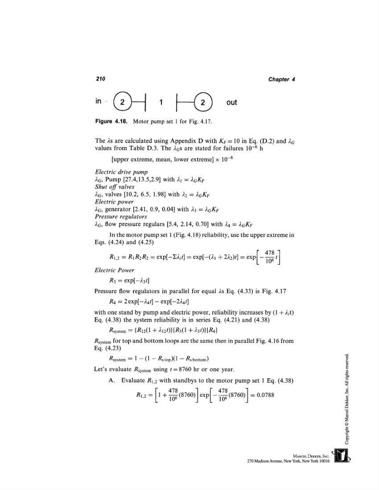
Figure 4.18. Motor pump set 1 for Fig. 4.17.
out
Chapter 4
The 2s are calculated using Appendix D with KF = 10 in Eq. (D.2) and
values from Table D.3. The 2as are stated for failures 10 -6 h
[upper extreme, mean, lower extreme] x 10
.6
Electric drive pump
26, Pump [27.4,13.5,2.9] with 21 ~ 26KF
Shut off valves
26, valves [10.2, 6.5, 1.98] with 22 = 26KF
Electric power
2c, generator [2.41, 0.9, 0.04] with 2 3 ~ 2GK F
Pressure regulators
26, flow pressure regulars [5.4, 2.14, 0.70] with 24 = 2cKF
In the motor pump set 1 (Fig. 4.18) reliability, use the upper extreme
Eqs. (4.24) and (4.25)
R1.2 = RIR2R2 = exp[-E2it] = exp[-(2j + 222)t] = exp
Electric Power
R3 = exp[-23t]
Pressure flow regulators in parallel for equal As Eq. (4.33) is Fig. 4.17
R4 = 2 exp[-24t] - exp[-224t]
with one stand by pump and electric power, reliability increases by (1 + J.it)
Eq. (4.38) the system reliability is in series Eq. (4.21) and (4.38)
Rsystem = {R12(1 -~-212t)}{R3(1 + 23t)}{R4}
Rsystem for top and bottom loops are the same then in parallel Fig. 4.16 from
Eq. (4.23)
Rsystem ~--- 1 -- (1 - Rstop)(1 -- Rsbottom)
Let’s evaluate Rsystem using t = 8760 hr or one year.
A. Evaluate R1,2 with standbys to the motor pump set 1 Eq. (4.38)
478
RI,2 = [1 + ~-~7068 (8760)] exp[-- ~ (8760)] = 0.0788
Figure 4.18. Motor pump set 1 for Fig. 4.17.
out
Chapter 4
The 2s are calculated using Appendix D with KF = 10 in Eq. (D.2) and
values from Table D.3. The 2as are stated for failures 10 -6 h
[upper extreme, mean, lower extreme] x 10
.6
Electric drive pump
26, Pump [27.4,13.5,2.9] with 21 ~ 26KF
Shut off valves
26, valves [10.2, 6.5, 1.98] with 22 = 26KF
Electric power
2c, generator [2.41, 0.9, 0.04] with 2 3 ~ 2GK F
Pressure regulators
26, flow pressure regulars [5.4, 2.14, 0.70] with 24 = 2cKF
In the motor pump set 1 (Fig. 4.18) reliability, use the upper extreme
Eqs. (4.24) and (4.25)
R1.2 = RIR2R2 = exp[-E2it] = exp[-(2j + 222)t] = exp
Electric Power
R3 = exp[-23t]
Pressure flow regulators in parallel for equal As Eq. (4.33) is Fig. 4.17
R4 = 2 exp[-24t] - exp[-224t]
with one stand by pump and electric power, reliability increases by (1 + J.it)
Eq. (4.38) the system reliability is in series Eq. (4.21) and (4.38)
Rsystem = {R12(1 -~-212t)}{R3(1 + 23t)}{R4}
Rsystem for top and bottom loops are the same then in parallel Fig. 4.16 from
Eq. (4.23)
Rsystem ~--- 1 -- (1 - Rstop)(1 -- Rsbottom)
Let’s evaluate Rsystem using t = 8760 hr or one year.
A. Evaluate R1,2 with standbys to the motor pump set 1 Eq. (4.38)
478
RI,2 = [1 + ~-~7068 (8760)] exp[-- ~ (8760)] = 0.0788