

Reliability
203
from Fig. 4.8 and a math handbook.
R(20 × 106) = 0.5 + 0.3413 + 0.1359 = 0.9772
Similarly,
R(40 × 106) = 0.5 - 0.3413 - 0.1359 = 0.0228
VI. CONFIGURATION EFFECTS ON RELIABILITY
A. Series System
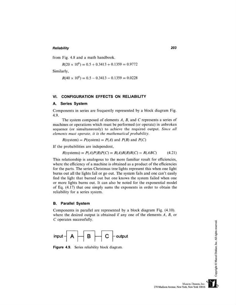
Components in series are frequently represented by a block diagram Fig.
4.9.
The system composed of elements A, B, and C represents a series of
machines or operations which must be performed (or operate) in unbroken
sequence (or simultaneously) to achieve the required output. Since all
elements must operate, it is the mathematical probability.
R(system) = P(system) P(A) and P(B) and P(C)
If the probabilities are independent,
R(systems) P(A)P(B)P(C) = R(A)R(B)R(C) = (4 .21)
This relationship is analogous to the more familiar result for efficiencies,
where the efficiency of a machine is obtained as a product of the efficiencies
for the parts. The series Christmas tree lights represent this when one light
burns out all the lights fail or go out. The system fails and one can’t easily
find the light that burned out but one knows the system failed when one
or more lights burns out. It can also be noted for the exponential model
of Eq. (4.17) that one simply sums the exponents in order to obtain the
reliability for a series system.
B. Parallel System
Components in parallel are represented by a block diagram Fig. (4.10).
where the desired output is obtained if any one of the elements A, B, or
C operates successfully.
input
~
output
Figure 4.9. Series reliability block diagram.
203
from Fig. 4.8 and a math handbook.
R(20 × 106) = 0.5 + 0.3413 + 0.1359 = 0.9772
Similarly,
R(40 × 106) = 0.5 - 0.3413 - 0.1359 = 0.0228
VI. CONFIGURATION EFFECTS ON RELIABILITY
A. Series System
Components in series are frequently represented by a block diagram Fig.
4.9.
The system composed of elements A, B, and C represents a series of
machines or operations which must be performed (or operate) in unbroken
sequence (or simultaneously) to achieve the required output. Since all
elements must operate, it is the mathematical probability.
R(system) = P(system) P(A) and P(B) and P(C)
If the probabilities are independent,
R(systems) P(A)P(B)P(C) = R(A)R(B)R(C) = (4 .21)
This relationship is analogous to the more familiar result for efficiencies,
where the efficiency of a machine is obtained as a product of the efficiencies
for the parts. The series Christmas tree lights represent this when one light
burns out all the lights fail or go out. The system fails and one can’t easily
find the light that burned out but one knows the system failed when one
or more lights burns out. It can also be noted for the exponential model
of Eq. (4.17) that one simply sums the exponents in order to obtain the
reliability for a series system.
B. Parallel System
Components in parallel are represented by a block diagram Fig. (4.10).
where the desired output is obtained if any one of the elements A, B, or
C operates successfully.
input
~
output
Figure 4.9. Series reliability block diagram.