

32.7 More About Incompatible Deformations
425
at the point D
−
∂u
∂y
x −
x
2
, y +
y
2
;
at the point A 2
−
∂u
∂y
x −
x
2
, y −
y
2
.
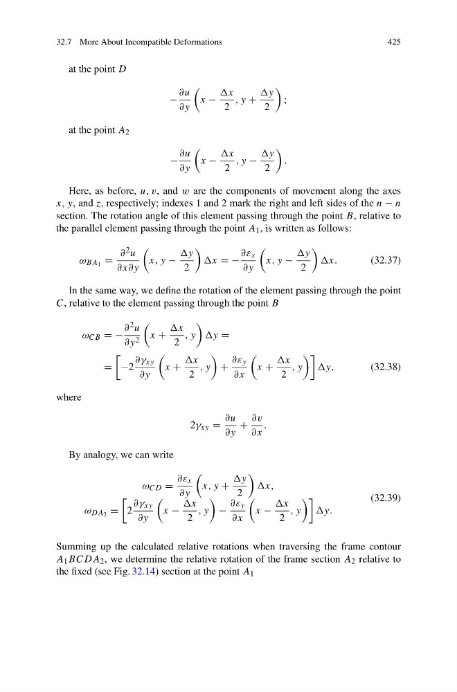
Here, as before, u, v, and w are the components of movement along the axes
x, y, and z, respectively; indexes 1 and 2 mark the right and left sides of the n − n
section. The rotation angle of this element passing through the point B, relative to
the parallel element passing through the point A 1 , is written as follows:
ω BA 1 =
∂ 2 u
∂x∂y
x, y −
y
2
x = −
∂ε x
∂y
x, y −
y
2
x.
(32.37)
In the same way, we define the rotation of the element passing through the point
C, relative to the element passing through the point B
ω CB = −
∂ 2 u
∂y 2
x +
x
2
, y
y =
=
−2
∂γ xy
∂y
x +
x
2
, y
+
∂ε y
∂x
x +
x
2
, y
y,
(32.38)
where
2γ xy =
∂u
∂y
+
∂v
∂x
.
By analogy, we can write
ω CD =
∂ε x
∂y
x, y +
y
2
x,
ω DA 2 =
2
∂γ xy
∂y
x −
x
2
, y
−
∂ε y
∂x
x −
x
2
, y
y.
(32.39)
Summing up the calculated relative rotations when traversing the frame contour
A 1 BCDA 2 , we determine the relative rotation of the frame section A 2 relative to
the fixed (see Fig. 32.14) section at the point A 1
425
at the point D
−
∂u
∂y
x −
x
2
, y +
y
2
;
at the point A 2
−
∂u
∂y
x −
x
2
, y −
y
2
.
Here, as before, u, v, and w are the components of movement along the axes
x, y, and z, respectively; indexes 1 and 2 mark the right and left sides of the n − n
section. The rotation angle of this element passing through the point B, relative to
the parallel element passing through the point A 1 , is written as follows:
ω BA 1 =
∂ 2 u
∂x∂y
x, y −
y
2
x = −
∂ε x
∂y
x, y −
y
2
x.
(32.37)
In the same way, we define the rotation of the element passing through the point
C, relative to the element passing through the point B
ω CB = −
∂ 2 u
∂y 2
x +
x
2
, y
y =
=
−2
∂γ xy
∂y
x +
x
2
, y
+
∂ε y
∂x
x +
x
2
, y
y,
(32.38)
where
2γ xy =
∂u
∂y
+
∂v
∂x
.
By analogy, we can write
ω CD =
∂ε x
∂y
x, y +
y
2
x,
ω DA 2 =
2
∂γ xy
∂y
x −
x
2
, y
−
∂ε y
∂x
x −
x
2
, y
y.
(32.39)
Summing up the calculated relative rotations when traversing the frame contour
A 1 BCDA 2 , we determine the relative rotation of the frame section A 2 relative to
the fixed (see Fig. 32.14) section at the point A 1