

14 Numerical Study on the Teeth Installation Parameters: Shift …
189
The second feature of the lower prosthesis basis is significant role of valve zone,
Fig. 14.2d. The physics of this valve zone appearance is related to adhesive forces
acting between tissue and prosthesis basis in the presence of viscous fluid (saliva).
The normal adhesive forces are assumed to be homogeneously distributed along the
prosthesis perimeter. These forces should be taken into an account during the vertical
displacement calculations.
The last outlining zone is retention zones that are located at the left and right
branches of the alveolar ridge. These zones are related to typical geometry of lower
jaw bone. The nature of these forces is similar to friction forces. The force is acting
in opposite direction of the local displacements. These boundary conditions are
corresponding to the main physical aspects of lower prosthesis behavior and used
for the present calculations.
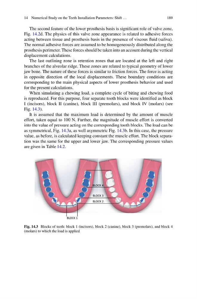
When simulating a chewing load, a complete cycle of biting and chewing food
is reproduced. For this purpose, four separate tooth blocks were identified as block
I (incisors), block II (canine), block III (premolars), and block IV (molars) (see
Fig. 14.3).
It is assumed that the maximum load is determined by the amount of muscle
effort, taken equal to 100 N. Further, the magnitude of muscle effort is converted
into the value of pressure acting on the corresponding tooth blocks. The load can be
as symmetrical, Fig. 14.3a, as well asymmetric Fig. 14.3b. In this case, the pressure
value, as before, is calculated keeping constant the muscle effort. The block separation was the same for the upper and lower jaw. The corresponding pressure values
are given in Table 14.2.
Fig. 14.3 Blocks of teeth: block 1 (incisors), block 2 (canine), block 3 (premolars), and block 4
(molars) to which the load is applied
189
The second feature of the lower prosthesis basis is significant role of valve zone,
Fig. 14.2d. The physics of this valve zone appearance is related to adhesive forces
acting between tissue and prosthesis basis in the presence of viscous fluid (saliva).
The normal adhesive forces are assumed to be homogeneously distributed along the
prosthesis perimeter. These forces should be taken into an account during the vertical
displacement calculations.
The last outlining zone is retention zones that are located at the left and right
branches of the alveolar ridge. These zones are related to typical geometry of lower
jaw bone. The nature of these forces is similar to friction forces. The force is acting
in opposite direction of the local displacements. These boundary conditions are
corresponding to the main physical aspects of lower prosthesis behavior and used
for the present calculations.
When simulating a chewing load, a complete cycle of biting and chewing food
is reproduced. For this purpose, four separate tooth blocks were identified as block
I (incisors), block II (canine), block III (premolars), and block IV (molars) (see
Fig. 14.3).
It is assumed that the maximum load is determined by the amount of muscle
effort, taken equal to 100 N. Further, the magnitude of muscle effort is converted
into the value of pressure acting on the corresponding tooth blocks. The load can be
as symmetrical, Fig. 14.3a, as well asymmetric Fig. 14.3b. In this case, the pressure
value, as before, is calculated keeping constant the muscle effort. The block separation was the same for the upper and lower jaw. The corresponding pressure values
are given in Table 14.2.
Fig. 14.3 Blocks of teeth: block 1 (incisors), block 2 (canine), block 3 (premolars), and block 4
(molars) to which the load is applied