

130
V. A. Obukhov et al.
Angles between the direction of the transversal and the axes of the SSC-associated
coordinate system being orthogonal to the longitudinal axis are considered as parameters for controlling the SSC lateral motion. When controlling the SSC-SDO relative
distance, a proportionally differentiating controller is applied that uses data on the
difference of the SSC-SDO relative distance from a certain average value, as well
as on the derivatives of the change in the relative distance. The lateral motion and
relative distance are controlled by the EPT rotation in two planes.
Turns of the EPS thrusters create momentums relative to the SSC-associated axes.
It is assumed that such momentums are compensated by the flywheels. On the other
hand, pivoted thrusters of EPS can in turn be used to unload the flywheels.
The aim of the work was to select the EPT arrangement on board SSC and develop
an algorithm for the EPT rotation control, which would allow for control actions
during the SDO transportation. The performance analysis of the EPT rotation control
algorithm was carried out by numerical modeling using a simplified model of IB
impact on SDO for different values of its parameters and algorithms of the SSC-SDO
cluster motion control.
10.3 Electric Propulsion Thruster Angle Control
Before a description of the thruster rotation angle control, the thruster layout onto
spacecraft-associated coordinate system is presented in Sect. 10.3.1. The thruster
rotation control algorithm is described in Sect. 10.3.2.
10.3.1 The Thruster Layout. Thrust Projections
onto the Axes of SSC-Associated Coordinate System
In this chapter, it is assumed that the SA axis is parallel to the axis OZ S of the SSCassociated coordinate system. It is assumed that the ranges of the EPT turn angles in
different planes may vary. In order to reduce the influence of the plasma plumes of
EPS on SA, the thrusters are located in OXY plane, orthogonally to the SA rotation
axis. With this, a larger range of angles of rotation is in OXY plane relative to the
axis Z. The first EPT rotation is carried out by an angle δ Z , while the second EPT
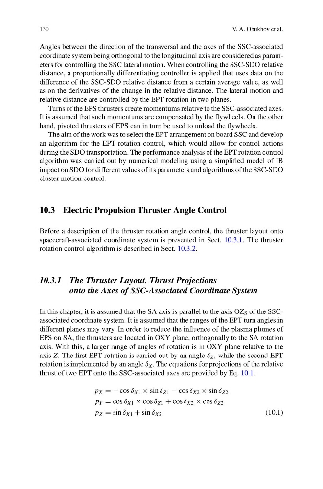
rotation is implemented by an angle δ X . The equations for projections of the relative
thrust of two EPT onto the SSC-associated axes are provided by Eq. 10.1.
p X = − cos δ X 1 × sin δ Z 1 − cos δ X 2 × sin δ Z 2
p Y = cos δ X 1 × cos δ Z 1 + cos δ X 2 × cos δ Z 2
p Z = sin δ X 1 + sin δ X 2
(10.1)
V. A. Obukhov et al.
Angles between the direction of the transversal and the axes of the SSC-associated
coordinate system being orthogonal to the longitudinal axis are considered as parameters for controlling the SSC lateral motion. When controlling the SSC-SDO relative
distance, a proportionally differentiating controller is applied that uses data on the
difference of the SSC-SDO relative distance from a certain average value, as well
as on the derivatives of the change in the relative distance. The lateral motion and
relative distance are controlled by the EPT rotation in two planes.
Turns of the EPS thrusters create momentums relative to the SSC-associated axes.
It is assumed that such momentums are compensated by the flywheels. On the other
hand, pivoted thrusters of EPS can in turn be used to unload the flywheels.
The aim of the work was to select the EPT arrangement on board SSC and develop
an algorithm for the EPT rotation control, which would allow for control actions
during the SDO transportation. The performance analysis of the EPT rotation control
algorithm was carried out by numerical modeling using a simplified model of IB
impact on SDO for different values of its parameters and algorithms of the SSC-SDO
cluster motion control.
10.3 Electric Propulsion Thruster Angle Control
Before a description of the thruster rotation angle control, the thruster layout onto
spacecraft-associated coordinate system is presented in Sect. 10.3.1. The thruster
rotation control algorithm is described in Sect. 10.3.2.
10.3.1 The Thruster Layout. Thrust Projections
onto the Axes of SSC-Associated Coordinate System
In this chapter, it is assumed that the SA axis is parallel to the axis OZ S of the SSCassociated coordinate system. It is assumed that the ranges of the EPT turn angles in
different planes may vary. In order to reduce the influence of the plasma plumes of
EPS on SA, the thrusters are located in OXY plane, orthogonally to the SA rotation
axis. With this, a larger range of angles of rotation is in OXY plane relative to the
axis Z. The first EPT rotation is carried out by an angle δ Z , while the second EPT
rotation is implemented by an angle δ X . The equations for projections of the relative
thrust of two EPT onto the SSC-associated axes are provided by Eq. 10.1.
p X = − cos δ X 1 × sin δ Z 1 − cos δ X 2 × sin δ Z 2
p Y = cos δ X 1 × cos δ Z 1 + cos δ X 2 × cos δ Z 2
p Z = sin δ X 1 + sin δ X 2
(10.1)