

10 Thruster Rotation Angle Control During Contactless Removal …
129
10.2 Problem Statement: Service Spacecraft Design
The problem of controlling the EPT rotation angles is considered for a given SSC
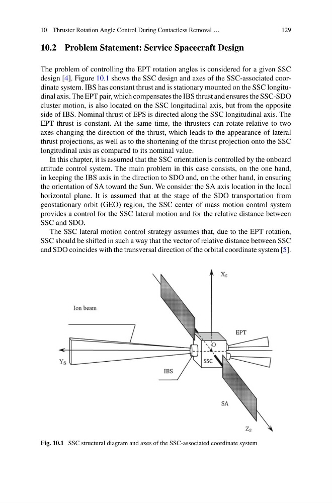
design [4]. Figure 10.1 shows the SSC design and axes of the SSC-associated coordinate system. IBS has constant thrust and is stationary mounted on the SSC longitudinal axis. The EPT pair, which compensates the IBS thrust and ensures the SSC-SDO
cluster motion, is also located on the SSC longitudinal axis, but from the opposite
side of IBS. Nominal thrust of EPS is directed along the SSC longitudinal axis. The
EPT thrust is constant. At the same time, the thrusters can rotate relative to two
axes changing the direction of the thrust, which leads to the appearance of lateral
thrust projections, as well as to the shortening of the thrust projection onto the SSC
longitudinal axis as compared to its nominal value.
In this chapter, it is assumed that the SSC orientation is controlled by the onboard
attitude control system. The main problem in this case consists, on the one hand,
in keeping the IBS axis in the direction to SDO and, on the other hand, in ensuring
the orientation of SA toward the Sun. We consider the SA axis location in the local
horizontal plane. It is assumed that at the stage of the SDO transportation from
geostationary orbit (GEO) region, the SSC center of mass motion control system
provides a control for the SSC lateral motion and for the relative distance between
SSC and SDO.
The SSC lateral motion control strategy assumes that, due to the EPT rotation,
SSC should be shifted in such a way that the vector of relative distance between SSC
and SDO coincides with the transversal direction of the orbital coordinate system [5].
Fig. 10.1 SSC structural diagram and axes of the SSC-associated coordinate system
129
10.2 Problem Statement: Service Spacecraft Design
The problem of controlling the EPT rotation angles is considered for a given SSC
design [4]. Figure 10.1 shows the SSC design and axes of the SSC-associated coordinate system. IBS has constant thrust and is stationary mounted on the SSC longitudinal axis. The EPT pair, which compensates the IBS thrust and ensures the SSC-SDO
cluster motion, is also located on the SSC longitudinal axis, but from the opposite
side of IBS. Nominal thrust of EPS is directed along the SSC longitudinal axis. The
EPT thrust is constant. At the same time, the thrusters can rotate relative to two
axes changing the direction of the thrust, which leads to the appearance of lateral
thrust projections, as well as to the shortening of the thrust projection onto the SSC
longitudinal axis as compared to its nominal value.
In this chapter, it is assumed that the SSC orientation is controlled by the onboard
attitude control system. The main problem in this case consists, on the one hand,
in keeping the IBS axis in the direction to SDO and, on the other hand, in ensuring
the orientation of SA toward the Sun. We consider the SA axis location in the local
horizontal plane. It is assumed that at the stage of the SDO transportation from
geostationary orbit (GEO) region, the SSC center of mass motion control system
provides a control for the SSC lateral motion and for the relative distance between
SSC and SDO.
The SSC lateral motion control strategy assumes that, due to the EPT rotation,
SSC should be shifted in such a way that the vector of relative distance between SSC
and SDO coincides with the transversal direction of the orbital coordinate system [5].
Fig. 10.1 SSC structural diagram and axes of the SSC-associated coordinate system