

74
3 Flow Rates and Pressure Measurements
TR 1
TR 2
t 1 t 2
t 2 >t 1
Airflow
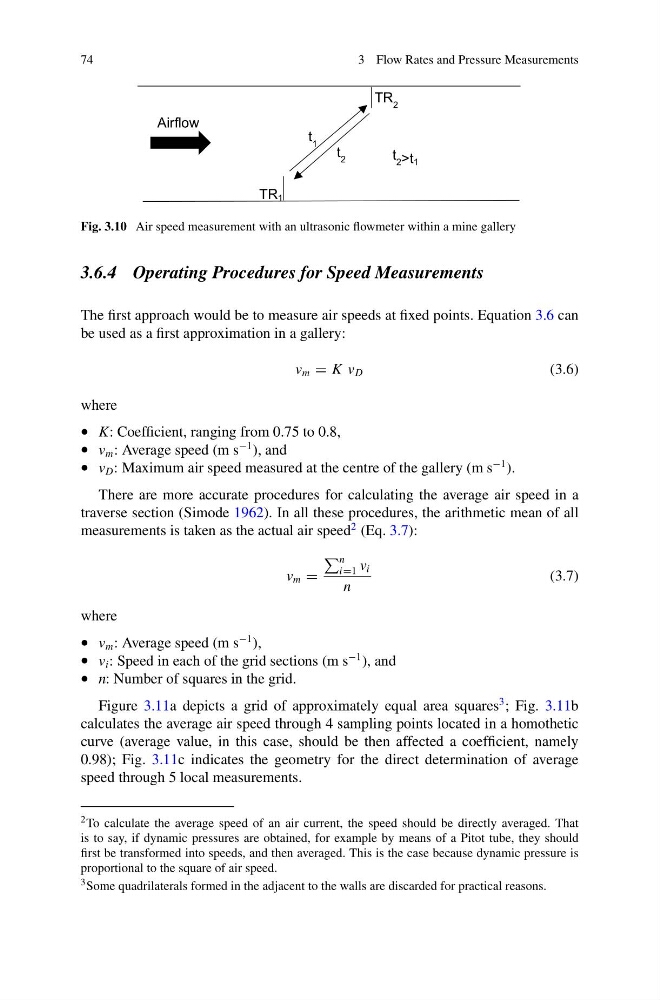
Fig. 3.10 Air speed measurement with an ultrasonic flowmeter within a mine gallery
3.6.4 Operating Procedures for Speed Measurements
The first approach would be to measure air speeds at fixed points. Equation 3.6 can
be used as a first approximation in a gallery:
v m = K v D
(3.6)
where
• K: Coefficient, ranging from 0.75 to 0.8,
• v m : Average speed (m s
−1 ), and
• v D : Maximum air speed measured at the centre of the gallery (m s
−1 ).
There are more accurate procedures for calculating the average air speed in a
traverse section (Simode 1962). In all these procedures, the arithmetic mean of all
measurements is taken as the actual air speed
2 (Eq. 3.7):
v m =
n
i=1 v i
n
(3.7)
where
• v m : Average speed (m s
−1 ),
• v i : Speed in each of the grid sections (m s
−1 ), and
• n: Number of squares in the grid.
Figure 3.11a depicts a grid of approximately equal area squares
3 ; Fig. 3.11b
calculates the average air speed through 4 sampling points located in a homothetic
curve (average value, in this case, should be then affected a coefficient, namely
0.98); Fig. 3.11c indicates the geometry for the direct determination of average
speed through 5 local measurements.
2 To calculate the average speed of an air current, the speed should be directly averaged. That
is to say, if dynamic pressures are obtained, for example by means of a Pitot tube, they should
first be transformed into speeds, and then averaged. This is the case because dynamic pressure is
proportional to the square of air speed.
3 Some quadrilaterals formed in the adjacent to the walls are discarded for practical reasons.
3 Flow Rates and Pressure Measurements
TR 1
TR 2
t 1 t 2
t 2 >t 1
Airflow
Fig. 3.10 Air speed measurement with an ultrasonic flowmeter within a mine gallery
3.6.4 Operating Procedures for Speed Measurements
The first approach would be to measure air speeds at fixed points. Equation 3.6 can
be used as a first approximation in a gallery:
v m = K v D
(3.6)
where
• K: Coefficient, ranging from 0.75 to 0.8,
• v m : Average speed (m s
−1 ), and
• v D : Maximum air speed measured at the centre of the gallery (m s
−1 ).
There are more accurate procedures for calculating the average air speed in a
traverse section (Simode 1962). In all these procedures, the arithmetic mean of all
measurements is taken as the actual air speed
2 (Eq. 3.7):
v m =
n
i=1 v i
n
(3.7)
where
• v m : Average speed (m s
−1 ),
• v i : Speed in each of the grid sections (m s
−1 ), and
• n: Number of squares in the grid.
Figure 3.11a depicts a grid of approximately equal area squares
3 ; Fig. 3.11b
calculates the average air speed through 4 sampling points located in a homothetic
curve (average value, in this case, should be then affected a coefficient, namely
0.98); Fig. 3.11c indicates the geometry for the direct determination of average
speed through 5 local measurements.
2 To calculate the average speed of an air current, the speed should be directly averaged. That
is to say, if dynamic pressures are obtained, for example by means of a Pitot tube, they should
first be transformed into speeds, and then averaged. This is the case because dynamic pressure is
proportional to the square of air speed.
3 Some quadrilaterals formed in the adjacent to the walls are discarded for practical reasons.