

3.6 Air Speed Measurement
73
3.6.2 Hot-Wire Anemometer
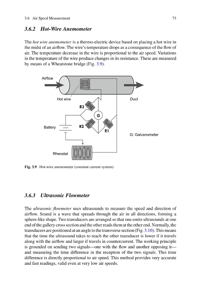
The hot wire anemometer is a thermo-electric device based on placing a hot wire in
the midst of an airflow. The wire’s temperature drops as a consequence of the flow of
air. The temperature decrease in the wire is proportional to the air speed. Variations
in the temperature of the wire produce changes in its resistance. These are measured
by means of a Wheatstone bridge (Fig. 3.9).
Airflow
Hot wire
Battery
Duct
Rheostat
G: Galvanometer
Fig. 3.9 Hot-wire anemometer (constant current system)
3.6.3 Ultrasonic Flowmeter
The ultrasonic flowmeter uses ultrasounds to measure the speed and direction of
airflow. Sound is a wave that spreads through the air in all directions, forming a
sphere-like shape. Two transducers are arranged so that one emits ultrasounds at one
end of the gallery cross section and the other reads them at the other end. Normally, the
transducers are positioned at an angle to the transverse section (Fig. 3.10). This means
that the time the ultrasound takes to reach the other transducer is lower if it travels
along with the airflow and larger if travels in countercurrent. The working principle
is grounded on sending two signals—one with the flow and another opposing it—
and measuring the time difference in the reception of the two signals. This time
difference is directly proportional to air speed. This method provides very accurate
and fast readings, valid even at very low air speeds.
73
3.6.2 Hot-Wire Anemometer
The hot wire anemometer is a thermo-electric device based on placing a hot wire in
the midst of an airflow. The wire’s temperature drops as a consequence of the flow of
air. The temperature decrease in the wire is proportional to the air speed. Variations
in the temperature of the wire produce changes in its resistance. These are measured
by means of a Wheatstone bridge (Fig. 3.9).
Airflow
Hot wire
Battery
Duct
Rheostat
G: Galvanometer
Fig. 3.9 Hot-wire anemometer (constant current system)
3.6.3 Ultrasonic Flowmeter
The ultrasonic flowmeter uses ultrasounds to measure the speed and direction of
airflow. Sound is a wave that spreads through the air in all directions, forming a
sphere-like shape. Two transducers are arranged so that one emits ultrasounds at one
end of the gallery cross section and the other reads them at the other end. Normally, the
transducers are positioned at an angle to the transverse section (Fig. 3.10). This means
that the time the ultrasound takes to reach the other transducer is lower if it travels
along with the airflow and larger if travels in countercurrent. The working principle
is grounded on sending two signals—one with the flow and another opposing it—
and measuring the time difference in the reception of the two signals. This time
difference is directly proportional to air speed. This method provides very accurate
and fast readings, valid even at very low air speeds.