

8.18 Sizing the Auxiliary Fan
367
This pressure is very low due to the fact that the cross-sectional area of the gallery
(A) is very large in comparison with that of the duct. Thus, it can be neglected.
(u) Total losses (P T ):
This is the sum of all losses previously calculated:
P T = P i + P sil + P f + P u + P c + P o + P r + P gr
= (298.5 + 120 + 1161.56 + 78.73
+ 298.4 + 335.78 + 135 + 0)Pa = 2427.97 Pa
(v) Corrected total pressure loss (P T c ):
The value obtained above should be corrected to take into account any possible
deterioration of the installation. For this purpose, we introduce a quality factor for
the installation (FC). In general:
• Bad quality: FC = 1.4
• Good quality: FC = 1.2
Assuming a good quality installation:
P T c = 1.2 · 2427.97 Pa = 2913.564 Pa
(w) Size of fan required:
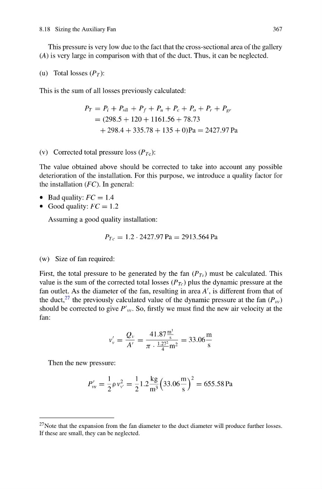
First, the total pressure to be generated by the fan (P Tv ) must be calculated. This
value is the sum of the corrected total losses (P Tc ) plus the dynamic pressure at the
fan outlet. As the diameter of the fan, resulting in area A
, is different from that of
the duct,
27 the previously calculated value of the dynamic pressure at the fan (P vv )
should be corrected to give P
vv . So, firstly we must find the new air velocity at the
fan:
v
v =
Q v
A =
41.87
m
3
s
π ·
1.27 2
4
m 2
= 33.06
m
s
Then the new pressure:
P
vv =
1
2
ρ v
2
v =
1
2
1.2
kg
m 3
33.06
m
s
2 = 655.58 Pa
27 Note that the expansion from the fan diameter to the duct diameter will produce further losses.
If these are small, they can be neglected.
367
This pressure is very low due to the fact that the cross-sectional area of the gallery
(A) is very large in comparison with that of the duct. Thus, it can be neglected.
(u) Total losses (P T ):
This is the sum of all losses previously calculated:
P T = P i + P sil + P f + P u + P c + P o + P r + P gr
= (298.5 + 120 + 1161.56 + 78.73
+ 298.4 + 335.78 + 135 + 0)Pa = 2427.97 Pa
(v) Corrected total pressure loss (P T c ):
The value obtained above should be corrected to take into account any possible
deterioration of the installation. For this purpose, we introduce a quality factor for
the installation (FC). In general:
• Bad quality: FC = 1.4
• Good quality: FC = 1.2
Assuming a good quality installation:
P T c = 1.2 · 2427.97 Pa = 2913.564 Pa
(w) Size of fan required:
First, the total pressure to be generated by the fan (P Tv ) must be calculated. This
value is the sum of the corrected total losses (P Tc ) plus the dynamic pressure at the
fan outlet. As the diameter of the fan, resulting in area A
, is different from that of
the duct,
27 the previously calculated value of the dynamic pressure at the fan (P vv )
should be corrected to give P
vv . So, firstly we must find the new air velocity at the
fan:
v
v =
Q v
A =
41.87
m
3
s
π ·
1.27 2
4
m 2
= 33.06
m
s
Then the new pressure:
P
vv =
1
2
ρ v
2
v =
1
2
1.2
kg
m 3
33.06
m
s
2 = 655.58 Pa
27 Note that the expansion from the fan diameter to the duct diameter will produce further losses.
If these are small, they can be neglected.