

366
8 Secondary Ventilation
P u =
K O L u Q
2
A 3
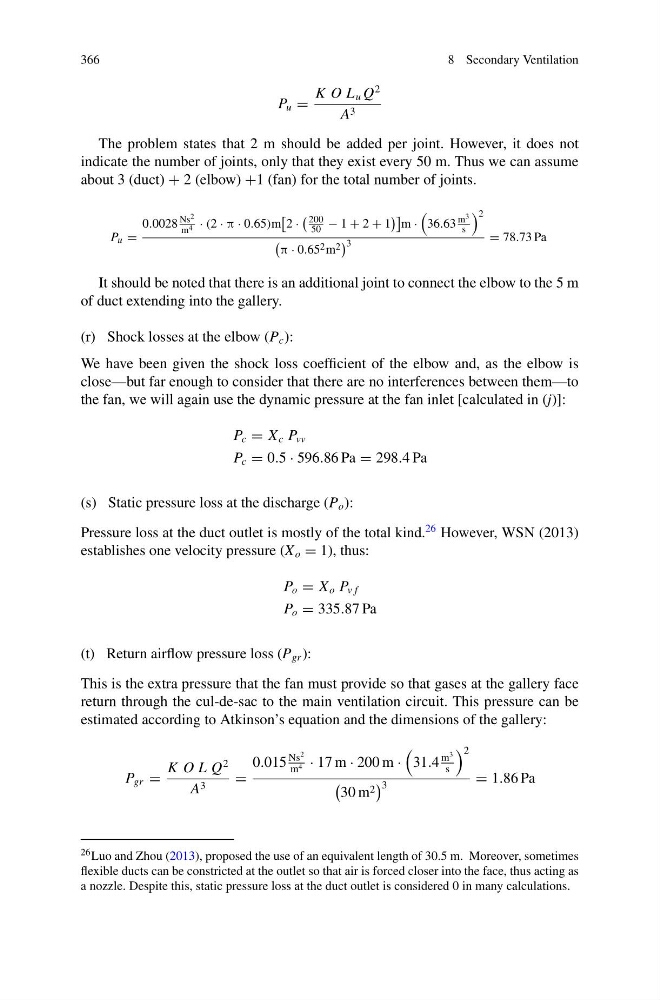
The problem states that 2 m should be added per joint. However, it does not
indicate the number of joints, only that they exist every 50 m. Thus we can assume
about 3 (duct) + 2 (elbow) +1 (fan) for the total number of joints.
P u =
0.0028
Ns 2
m 4 · (2 · π · 0.65)m
2 ·
200
50 − 1 + 2 + 1
m ·
36.63
m 3
s
2
π · 0.65 2 m 2
3
= 78.73 Pa
It should be noted that there is an additional joint to connect the elbow to the 5 m
of duct extending into the gallery.
(r) Shock losses at the elbow (P c ):
We have been given the shock loss coefficient of the elbow and, as the elbow is
close—but far enough to consider that there are no interferences between them—to
the fan, we will again use the dynamic pressure at the fan inlet [calculated in (j)]:
P c = X c P vv
P c = 0.5 · 596.86 Pa = 298.4 Pa
(s) Static pressure loss at the discharge (P o ):
Pressure loss at the duct outlet is mostly of the total kind.
26 However, WSN (2013)
establishes one velocity pressure (X o = 1), thus:
P o = X o P v f
P o = 335.87 Pa
(t) Return airflow pressure loss (P gr ):
This is the extra pressure that the fan must provide so that gases at the gallery face
return through the cul-de-sac to the main ventilation circuit. This pressure can be
estimated according to Atkinson’s equation and the dimensions of the gallery:
P gr =
K O L Q
2
A 3
=
0.015
Ns
2
m 4 · 17 m · 200 m ·
31.4
m
3
s
2
30 m 2
3
= 1.86 Pa
26 Luo and Zhou (2013), proposed the use of an equivalent length of 30.5 m. Moreover, sometimes
flexible ducts can be constricted at the outlet so that air is forced closer into the face, thus acting as
a nozzle. Despite this, static pressure loss at the duct outlet is considered 0 in many calculations.
8 Secondary Ventilation
P u =
K O L u Q
2
A 3
The problem states that 2 m should be added per joint. However, it does not
indicate the number of joints, only that they exist every 50 m. Thus we can assume
about 3 (duct) + 2 (elbow) +1 (fan) for the total number of joints.
P u =
0.0028
Ns 2
m 4 · (2 · π · 0.65)m
2 ·
200
50 − 1 + 2 + 1
m ·
36.63
m 3
s
2
π · 0.65 2 m 2
3
= 78.73 Pa
It should be noted that there is an additional joint to connect the elbow to the 5 m
of duct extending into the gallery.
(r) Shock losses at the elbow (P c ):
We have been given the shock loss coefficient of the elbow and, as the elbow is
close—but far enough to consider that there are no interferences between them—to
the fan, we will again use the dynamic pressure at the fan inlet [calculated in (j)]:
P c = X c P vv
P c = 0.5 · 596.86 Pa = 298.4 Pa
(s) Static pressure loss at the discharge (P o ):
Pressure loss at the duct outlet is mostly of the total kind.
26 However, WSN (2013)
establishes one velocity pressure (X o = 1), thus:
P o = X o P v f
P o = 335.87 Pa
(t) Return airflow pressure loss (P gr ):
This is the extra pressure that the fan must provide so that gases at the gallery face
return through the cul-de-sac to the main ventilation circuit. This pressure can be
estimated according to Atkinson’s equation and the dimensions of the gallery:
P gr =
K O L Q
2
A 3
=
0.015
Ns
2
m 4 · 17 m · 200 m ·
31.4
m
3
s
2
30 m 2
3
= 1.86 Pa
26 Luo and Zhou (2013), proposed the use of an equivalent length of 30.5 m. Moreover, sometimes
flexible ducts can be constricted at the outlet so that air is forced closer into the face, thus acting as
a nozzle. Despite this, static pressure loss at the duct outlet is considered 0 in many calculations.