

8.18 Sizing the Auxiliary Fan
363
(k) Average airflow in the duct:
As we have seen, leaks cause variation in the volumetric flow rate along a duct. This
is because leakage reduces air velocity, and therefore, dynamic pressure. In the leaky
duct, the average flow rate is usually calculated as the geometric mean of the flow
rates at each end (Eq. 8.61):
Q =
2
Q f Q v
Q =
2
31.4
m 3
s
· 41.86
m 3
s
= 36.25
m
3
s
Another way to approach this is by using Eq. 8.62:
Q = Q f + 0.5 Q loss = 31.4
m
3
s
+ 0.5(41.86 − 31.4)
m
3
s
= 36.63
m
3
s
Pressure losses in the system (items l to v)
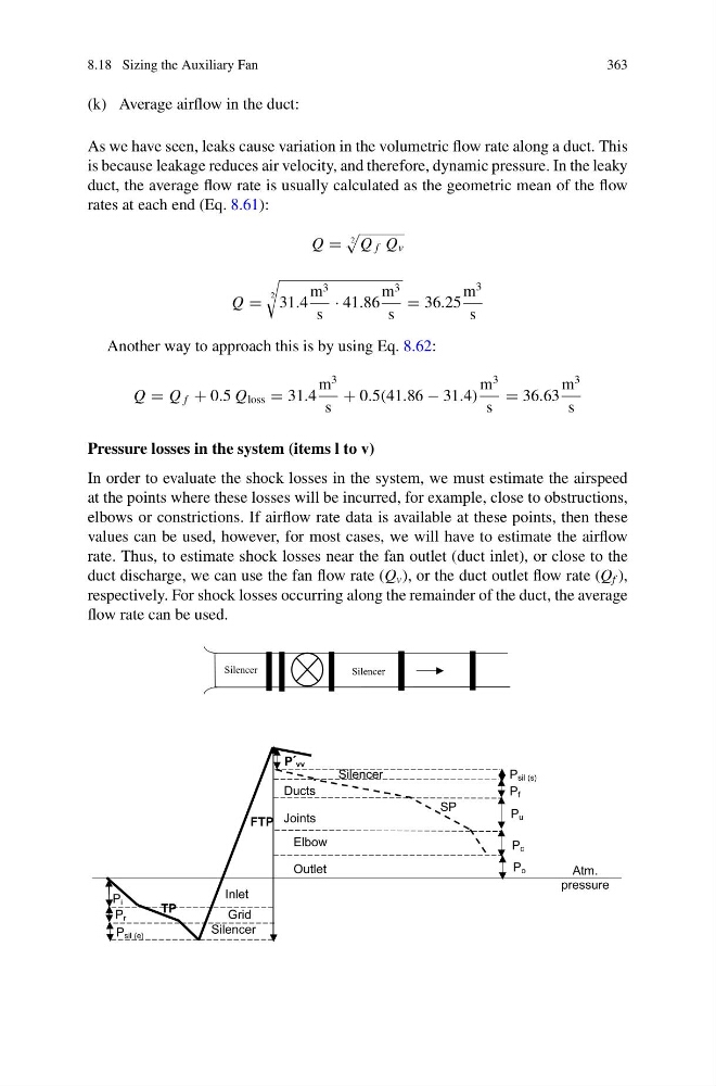
In order to evaluate the shock losses in the system, we must estimate the airspeed
at the points where these losses will be incurred, for example, close to obstructions,
elbows or constrictions. If airflow rate data is available at these points, then these
values can be used, however, for most cases, we will have to estimate the airflow
rate. Thus, to estimate shock losses near the fan outlet (duct inlet), or close to the
duct discharge, we can use the fan flow rate (Q v ), or the duct outlet flow rate (Q f ),
respectively. For shock losses occurring along the remainder of the duct, the average
flow rate can be used.
Silencer
Silencer
Inlet
Grid
Silencer
TP
FTP
SP
Ducts
Joints
Elbow
Outlet
P vv
P i
P r
P sil (e)
P f
P u
P c
P o
Silencer
P sil (s)
Atm.
pressure
363
(k) Average airflow in the duct:
As we have seen, leaks cause variation in the volumetric flow rate along a duct. This
is because leakage reduces air velocity, and therefore, dynamic pressure. In the leaky
duct, the average flow rate is usually calculated as the geometric mean of the flow
rates at each end (Eq. 8.61):
Q =
2
Q f Q v
Q =
2
31.4
m 3
s
· 41.86
m 3
s
= 36.25
m
3
s
Another way to approach this is by using Eq. 8.62:
Q = Q f + 0.5 Q loss = 31.4
m
3
s
+ 0.5(41.86 − 31.4)
m
3
s
= 36.63
m
3
s
Pressure losses in the system (items l to v)
In order to evaluate the shock losses in the system, we must estimate the airspeed
at the points where these losses will be incurred, for example, close to obstructions,
elbows or constrictions. If airflow rate data is available at these points, then these
values can be used, however, for most cases, we will have to estimate the airflow
rate. Thus, to estimate shock losses near the fan outlet (duct inlet), or close to the
duct discharge, we can use the fan flow rate (Q v ), or the duct outlet flow rate (Q f ),
respectively. For shock losses occurring along the remainder of the duct, the average
flow rate can be used.
Silencer
Silencer
Inlet
Grid
Silencer
TP
FTP
SP
Ducts
Joints
Elbow
Outlet
P vv
P i
P r
P sil (e)
P f
P u
P c
P o
Silencer
P sil (s)
Atm.
pressure