

362
8 Secondary Ventilation
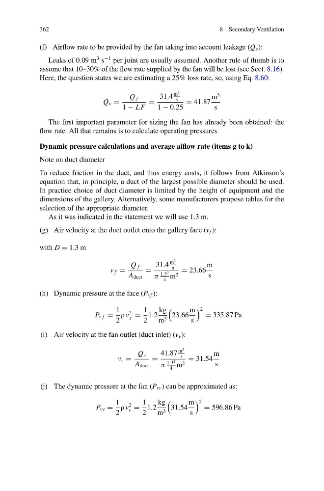
(f) Airflow rate to be provided by the fan taking into account leakage (Q v ):
Leaks of 0.09 m
3 s
−1 per joint are usually assumed. Another rule of thumb is to
assume that 10–30% of the flow rate supplied by the fan will be lost (see Sect. 8.16).
Here, the question states we are estimating a 25% loss rate, so, using Eq. 8.60:
Q v =
Q f
1 − L F
=
31.4
m
3
s
1 − 0.25
= 41.87
m
3
s
The first important parameter for sizing the fan has already been obtained: the
flow rate. All that remains is to calculate operating pressures.
Dynamic pressure calculations and average aiflow rate (items g to k)
Note on duct diameter
To reduce friction in the duct, and thus energy costs, it follows from Atkinson’s
equation that, in principle, a duct of the largest possible diameter should be used.
In practice choice of duct diameter is limited by the height of equipment and the
dimensions of the gallery. Alternatively, some manufacturers propose tables for the
selection of the appropriate diameter.
As it was indicated in the statement we will use 1.3 m.
(g) Air velocity at the duct outlet onto the gallery face (v f ):
with D = 1.3 m
v f =
Q f
A duct
=
31.4
m
3
s
π
1.3 2
4
m 2
= 23.66
m
s
(h) Dynamic pressure at the face (P vf ):
P v f =
1
2
ρ v
2
f =
1
2
1.2
kg
m 3
23.66
m
s
2 = 335.87 Pa
(i) Air velocity at the fan outlet (duct inlet) (v v ):
v v =
Q v
A duct
=
41.87
m
3
s
π
1.3 2
4
m 2
= 31.54
m
s
(j) The dynamic pressure at the fan (P vv ) can be approximated as:
P vv =
1
2
ρ v
2
v =
1
2
1.2
kg
m 3
31.54
m
s
2 = 596.86 Pa
8 Secondary Ventilation
(f) Airflow rate to be provided by the fan taking into account leakage (Q v ):
Leaks of 0.09 m
3 s
−1 per joint are usually assumed. Another rule of thumb is to
assume that 10–30% of the flow rate supplied by the fan will be lost (see Sect. 8.16).
Here, the question states we are estimating a 25% loss rate, so, using Eq. 8.60:
Q v =
Q f
1 − L F
=
31.4
m
3
s
1 − 0.25
= 41.87
m
3
s
The first important parameter for sizing the fan has already been obtained: the
flow rate. All that remains is to calculate operating pressures.
Dynamic pressure calculations and average aiflow rate (items g to k)
Note on duct diameter
To reduce friction in the duct, and thus energy costs, it follows from Atkinson’s
equation that, in principle, a duct of the largest possible diameter should be used.
In practice choice of duct diameter is limited by the height of equipment and the
dimensions of the gallery. Alternatively, some manufacturers propose tables for the
selection of the appropriate diameter.
As it was indicated in the statement we will use 1.3 m.
(g) Air velocity at the duct outlet onto the gallery face (v f ):
with D = 1.3 m
v f =
Q f
A duct
=
31.4
m
3
s
π
1.3 2
4
m 2
= 23.66
m
s
(h) Dynamic pressure at the face (P vf ):
P v f =
1
2
ρ v
2
f =
1
2
1.2
kg
m 3
23.66
m
s
2 = 335.87 Pa
(i) Air velocity at the fan outlet (duct inlet) (v v ):
v v =
Q v
A duct
=
41.87
m
3
s
π
1.3 2
4
m 2
= 31.54
m
s
(j) The dynamic pressure at the fan (P vv ) can be approximated as:
P vv =
1
2
ρ v
2
v =
1
2
1.2
kg
m 3
31.54
m
s
2 = 596.86 Pa