

354
8 Secondary Ventilation
• B: Equivalent duct length
22 :
The actual length of the duct
+
1.83 m (6 feet) equivalent length per coupling
+
30.5 m (100 feet) equivalent length for exit losses
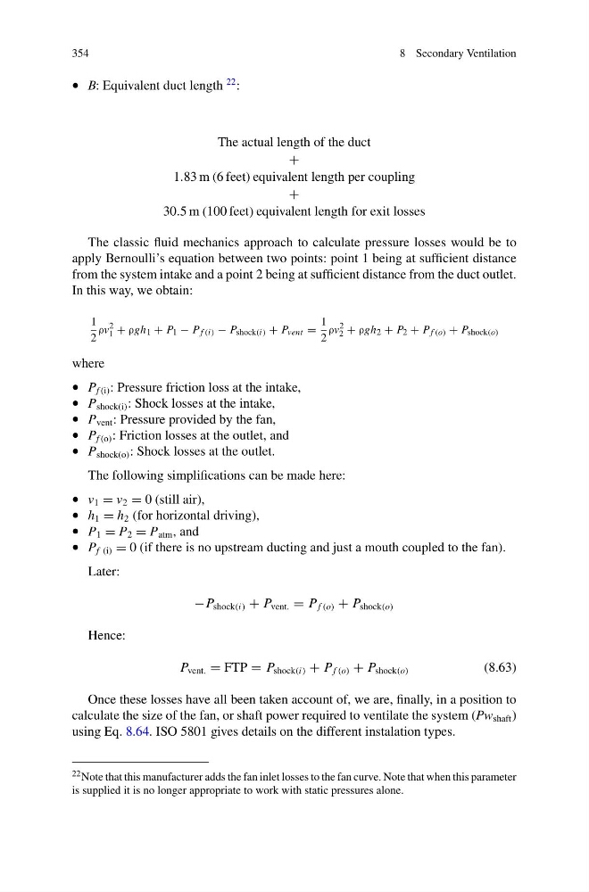
The classic fluid mechanics approach to calculate pressure losses would be to
apply Bernoulli’s equation between two points: point 1 being at sufficient distance
from the system intake and a point 2 being at sufficient distance from the duct outlet.
In this way, we obtain:
1
2
ρv
2
1 + ρgh 1 + P 1 − P f (i) − P shock(i) + P vent =
1
2
ρv
2
2 + ρgh 2 + P 2 + P f (o) + P shock(o)
where
• P f (i) : Pressure friction loss at the intake,
• P shock(i) : Shock losses at the intake,
• P vent : Pressure provided by the fan,
• P f (o) : Friction losses at the outlet, and
• P shock(o) : Shock losses at the outlet.
The following simplifications can be made here:
• v 1 = v 2 = 0 (still air),
• h 1 = h 2 (for horizontal driving),
• P 1 = P 2 = P atm , and
• P f (i) = 0 (if there is no upstream ducting and just a mouth coupled to the fan).
Later:
−P shock(i) + P vent. = P f (o) + P shock(o)
Hence:
P vent. = FTP = P shock(i) + P f (o) + P shock(o)
(8.63)
Once these losses have all been taken account of, we are, finally, in a position to
calculate the size of the fan, or shaft power required to ventilate the system (Pw shaft )
using Eq. 8.64. ISO 5801 gives details on the different instalation types.
22 Note that this manufacturer adds the fan inlet losses to the fan curve. Note that when this parameter
is supplied it is no longer appropriate to work with static pressures alone.
8 Secondary Ventilation
• B: Equivalent duct length
22 :
The actual length of the duct
+
1.83 m (6 feet) equivalent length per coupling
+
30.5 m (100 feet) equivalent length for exit losses
The classic fluid mechanics approach to calculate pressure losses would be to
apply Bernoulli’s equation between two points: point 1 being at sufficient distance
from the system intake and a point 2 being at sufficient distance from the duct outlet.
In this way, we obtain:
1
2
ρv
2
1 + ρgh 1 + P 1 − P f (i) − P shock(i) + P vent =
1
2
ρv
2
2 + ρgh 2 + P 2 + P f (o) + P shock(o)
where
• P f (i) : Pressure friction loss at the intake,
• P shock(i) : Shock losses at the intake,
• P vent : Pressure provided by the fan,
• P f (o) : Friction losses at the outlet, and
• P shock(o) : Shock losses at the outlet.
The following simplifications can be made here:
• v 1 = v 2 = 0 (still air),
• h 1 = h 2 (for horizontal driving),
• P 1 = P 2 = P atm , and
• P f (i) = 0 (if there is no upstream ducting and just a mouth coupled to the fan).
Later:
−P shock(i) + P vent. = P f (o) + P shock(o)
Hence:
P vent. = FTP = P shock(i) + P f (o) + P shock(o)
(8.63)
Once these losses have all been taken account of, we are, finally, in a position to
calculate the size of the fan, or shaft power required to ventilate the system (Pw shaft )
using Eq. 8.64. ISO 5801 gives details on the different instalation types.
22 Note that this manufacturer adds the fan inlet losses to the fan curve. Note that when this parameter
is supplied it is no longer appropriate to work with static pressures alone.