

8.18 Sizing the Auxiliary Fan
353
FTP
1P v
P T
P e
FVP
Pressure
Distance
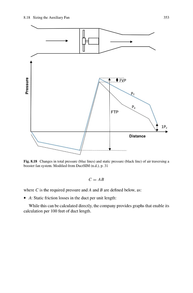
Fig. 8.18 Changes in total pressure (blue lines) and static pressure (black line) of air traversing a
booster fan system. Modified from DuctSIM (n.d.), p. 31
C = AB
where C is the required pressure and A and B are defined below, as:
• A: Static friction losses in the duct per unit length:
While this can be calculated directly, the company provides graphs that enable its
calculation per 100 feet of duct length.
353
FTP
1P v
P T
P e
FVP
Pressure
Distance
Fig. 8.18 Changes in total pressure (blue lines) and static pressure (black line) of air traversing a
booster fan system. Modified from DuctSIM (n.d.), p. 31
C = AB
where C is the required pressure and A and B are defined below, as:
• A: Static friction losses in the duct per unit length:
While this can be calculated directly, the company provides graphs that enable its
calculation per 100 feet of duct length.