

8.18 Sizing the Auxiliary Fan
351
8.18 Sizing the Auxiliary Fan
When selecting an auxiliary fan, the following must be considered, at least:
(a) The location of the fan with respect to the ducting (forcing, exhausting or
booster).
(b) The type of secondary ventilation layout (forcing, exhausting, mixed or
overlapped).
(c) The number of fans along the ducting (single, double, multiple).
(d) And whether static or total pressures are to be used for the sizing calculations.
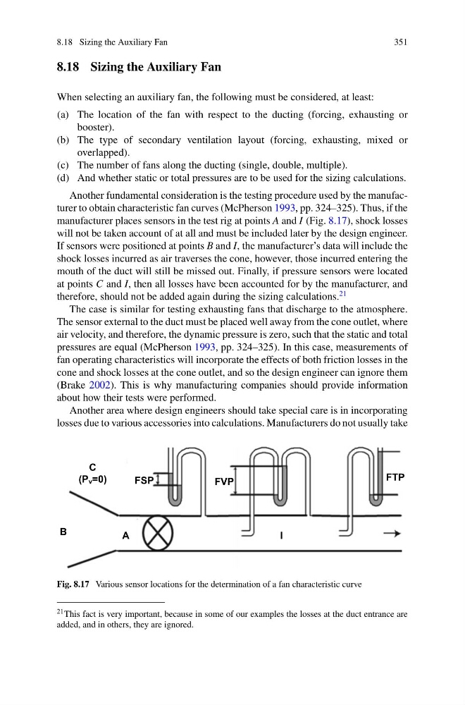
Another fundamental consideration is the testing procedure used by the manufacturer to obtain characteristic fan curves (McPherson 1993, pp. 324–325). Thus, if the
manufacturer places sensors in the test rig at points A and I (Fig. 8.17), shock losses
will not be taken account of at all and must be included later by the design engineer.
If sensors were positioned at points B and I, the manufacturer’s data will include the
shock losses incurred as air traverses the cone, however, those incurred entering the
mouth of the duct will still be missed out. Finally, if pressure sensors were located
at points C and I, then all losses have been accounted for by the manufacturer, and
therefore, should not be added again during the sizing calculations.
21
The case is similar for testing exhausting fans that discharge to the atmosphere.
The sensor external to the duct must be placed well away from the cone outlet, where
air velocity, and therefore, the dynamic pressure is zero, such that the static and total
pressures are equal (McPherson 1993, pp. 324–325). In this case, measurements of
fan operating characteristics will incorporate the effects of both friction losses in the
cone and shock losses at the cone outlet, and so the design engineer can ignore them
(Brake 2002). This is why manufacturing companies should provide information
about how their tests were performed.
Another area where design engineers should take special care is in incorporating
losses due to various accessories into calculations. Manufacturers do not usually take
FSP
FVP
FTP
C
(P v =0)
B
A
I
Fig. 8.17 Various sensor locations for the determination of a fan characteristic curve
21 This fact is very important, because in some of our examples the losses at the duct entrance are
added, and in others, they are ignored.
351
8.18 Sizing the Auxiliary Fan
When selecting an auxiliary fan, the following must be considered, at least:
(a) The location of the fan with respect to the ducting (forcing, exhausting or
booster).
(b) The type of secondary ventilation layout (forcing, exhausting, mixed or
overlapped).
(c) The number of fans along the ducting (single, double, multiple).
(d) And whether static or total pressures are to be used for the sizing calculations.
Another fundamental consideration is the testing procedure used by the manufacturer to obtain characteristic fan curves (McPherson 1993, pp. 324–325). Thus, if the
manufacturer places sensors in the test rig at points A and I (Fig. 8.17), shock losses
will not be taken account of at all and must be included later by the design engineer.
If sensors were positioned at points B and I, the manufacturer’s data will include the
shock losses incurred as air traverses the cone, however, those incurred entering the
mouth of the duct will still be missed out. Finally, if pressure sensors were located
at points C and I, then all losses have been accounted for by the manufacturer, and
therefore, should not be added again during the sizing calculations.
21
The case is similar for testing exhausting fans that discharge to the atmosphere.
The sensor external to the duct must be placed well away from the cone outlet, where
air velocity, and therefore, the dynamic pressure is zero, such that the static and total
pressures are equal (McPherson 1993, pp. 324–325). In this case, measurements of
fan operating characteristics will incorporate the effects of both friction losses in the
cone and shock losses at the cone outlet, and so the design engineer can ignore them
(Brake 2002). This is why manufacturing companies should provide information
about how their tests were performed.
Another area where design engineers should take special care is in incorporating
losses due to various accessories into calculations. Manufacturers do not usually take
FSP
FVP
FTP
C
(P v =0)
B
A
I
Fig. 8.17 Various sensor locations for the determination of a fan characteristic curve
21 This fact is very important, because in some of our examples the losses at the duct entrance are
added, and in others, they are ignored.