

346
8 Secondary Ventilation
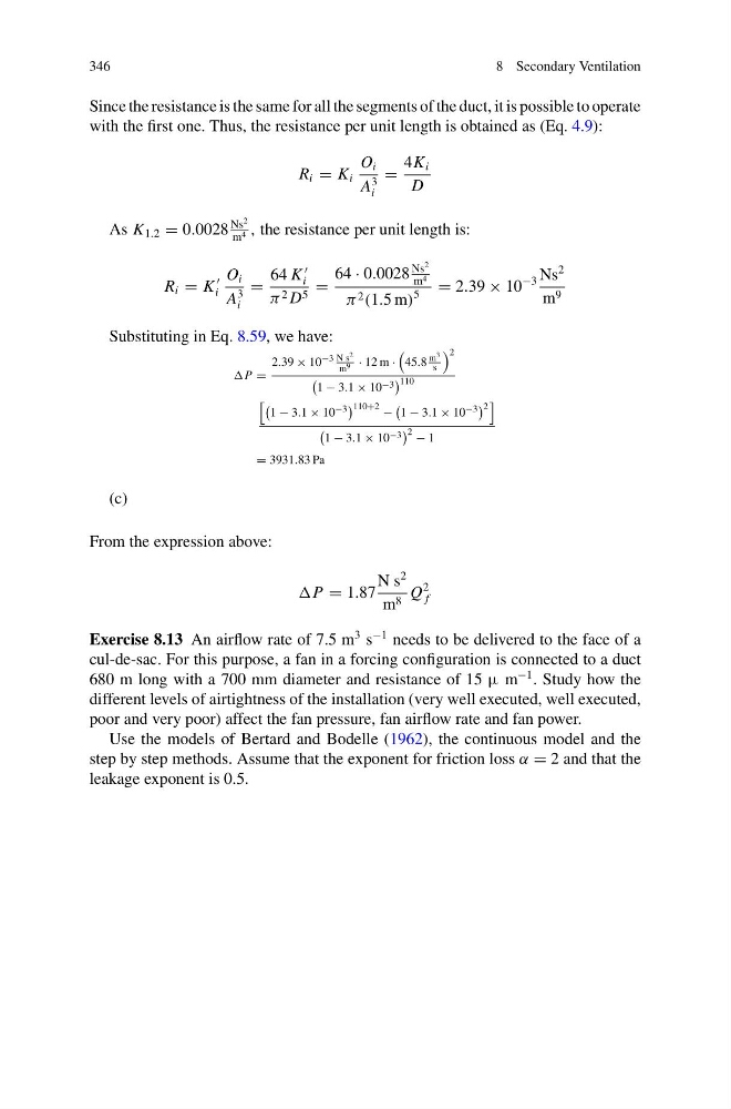
Since the resistance is the same for all the segments of the duct, it is possible to operate
with the first one. Thus, the resistance per unit length is obtained as (Eq. 4.9):
R i = K i
O i
A
3
i
=
4K i
D
As K 1.2 = 0.0028
Ns
2
m 4 , the resistance per unit length is:
R i = K
i
O i
A
3
i
=
64 K
i
π 2 D 5 =
64 · 0.0028
Ns
2
m 4
π 2 (1.5 m)
5
= 2.39 × 10
−3 Ns
2
m 9
Substituting in Eq. 8.59, we have:
P =
2.39 × 10 −3 N s 2
m 9 · 12 m ·
45.8
m 3
s
2
1 − 3.1 × 10 −3
110
1 − 3.1 × 10 −3 110+2 −
1 − 3.1 × 10 −3 2
1 − 3.1 × 10 −3
2 − 1
= 3931.83 Pa
(c)
From the expression above:
P = 1.87
N s
2
m 8 Q
2
f
Exercise 8.13 An airflow rate of 7.5 m
3 s
−1 needs to be delivered to the face of a
cul-de-sac. For this purpose, a fan in a forcing configuration is connected to a duct
680 m long with a 700 mm diameter and resistance of 15 μ m
−1 . Study how the
different levels of airtightness of the installation (very well executed, well executed,
poor and very poor) affect the fan pressure, fan airflow rate and fan power.
Use the models of Bertard and Bodelle (1962), the continuous model and the
step by step methods. Assume that the exponent for friction loss α = 2 and that the
leakage exponent is 0.5.
8 Secondary Ventilation
Since the resistance is the same for all the segments of the duct, it is possible to operate
with the first one. Thus, the resistance per unit length is obtained as (Eq. 4.9):
R i = K i
O i
A
3
i
=
4K i
D
As K 1.2 = 0.0028
Ns
2
m 4 , the resistance per unit length is:
R i = K
i
O i
A
3
i
=
64 K
i
π 2 D 5 =
64 · 0.0028
Ns
2
m 4
π 2 (1.5 m)
5
= 2.39 × 10
−3 Ns
2
m 9
Substituting in Eq. 8.59, we have:
P =
2.39 × 10 −3 N s 2
m 9 · 12 m ·
45.8
m 3
s
2
1 − 3.1 × 10 −3
110
1 − 3.1 × 10 −3 110+2 −
1 − 3.1 × 10 −3 2
1 − 3.1 × 10 −3
2 − 1
= 3931.83 Pa
(c)
From the expression above:
P = 1.87
N s
2
m 8 Q
2
f
Exercise 8.13 An airflow rate of 7.5 m
3 s
−1 needs to be delivered to the face of a
cul-de-sac. For this purpose, a fan in a forcing configuration is connected to a duct
680 m long with a 700 mm diameter and resistance of 15 μ m
−1 . Study how the
different levels of airtightness of the installation (very well executed, well executed,
poor and very poor) affect the fan pressure, fan airflow rate and fan power.
Use the models of Bertard and Bodelle (1962), the continuous model and the
step by step methods. Assume that the exponent for friction loss α = 2 and that the
leakage exponent is 0.5.