

296
8 Secondary Ventilation
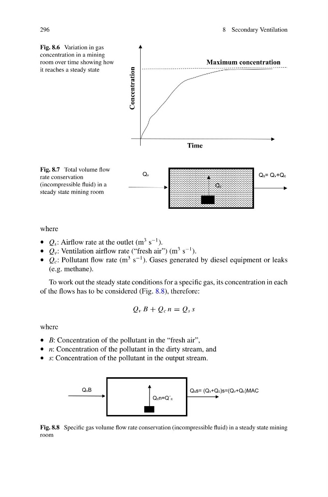
Fig. 8.6 Variation in gas
concentration in a mining
room over time showing how
it reaches a steady state
Concentration
Time
Maximum concentration
Fig. 8.7 Total volume flow
rate conservation
(incompressible fluid) in a
steady state mining room
Qc
Qv
Qs= Qv+Qc
where
• Q s : Airflow rate at the outlet (m
3 s
−1 ).
• Q v : Ventilation airflow rate (“fresh air”) (m
3 s
−1 ).
• Q c : Pollutant flow rate (m
3 s
−1 ). Gases generated by diesel equipment or leaks
(e.g. methane).
To work out the steady state conditions for a specific gas, its concentration in each
of the flows has to be considered (Fig. 8.8), therefore:
Q v B + Q c n = Q s s
where
• B: Concentration of the pollutant in the “fresh air”,
• n: Concentration of the pollutant in the dirty stream, and
• s: Concentration of the pollutant in the output stream.
Qcn=Q´c
QvB
Qss= (Qv+Qc)s=(Qv+Qc)MAC
Fig. 8.8 Specific gas volume flow rate conservation (incompressible fluid) in a steady state mining
room
8 Secondary Ventilation
Fig. 8.6 Variation in gas
concentration in a mining
room over time showing how
it reaches a steady state
Concentration
Time
Maximum concentration
Fig. 8.7 Total volume flow
rate conservation
(incompressible fluid) in a
steady state mining room
Qc
Qv
Qs= Qv+Qc
where
• Q s : Airflow rate at the outlet (m
3 s
−1 ).
• Q v : Ventilation airflow rate (“fresh air”) (m
3 s
−1 ).
• Q c : Pollutant flow rate (m
3 s
−1 ). Gases generated by diesel equipment or leaks
(e.g. methane).
To work out the steady state conditions for a specific gas, its concentration in each
of the flows has to be considered (Fig. 8.8), therefore:
Q v B + Q c n = Q s s
where
• B: Concentration of the pollutant in the “fresh air”,
• n: Concentration of the pollutant in the dirty stream, and
• s: Concentration of the pollutant in the output stream.
Qcn=Q´c
QvB
Qss= (Qv+Qc)s=(Qv+Qc)MAC
Fig. 8.8 Specific gas volume flow rate conservation (incompressible fluid) in a steady state mining
room