

7.7 Calculation of Critical Speed
267
Finally, parameter C is:
C =
g H
C =
√
8.81 · 3.5 = 5.8596
The condition of A > B is met, thus we can use Eq. 7.19:
V c = K g · 0.43 · C e
−
L b
18.5 H
= 1.1188 · 0.43 · 5.8596 e (−
0.0
18.5·3.5 ) = 2.82
m
s
Therefore, the ventilating air blown into the fire gallery must have a velocity
greater than 2.82 m s
−1 .
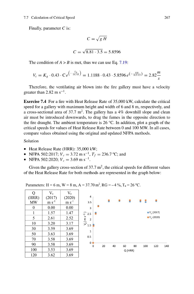
Exercise 7.4 For a fire with Heat Release Rate of 35,000 kW, calculate the critical
speed for a gallery with maximum height and width of 6 and 8 m, respectively, and
a cross-sectional area of 37.7 m
2 . The gallery has a 4% downhill slope and clean
air must be introduced downwards, to drag the fumes in the opposite direction to
the fire draught. The ambient temperature is 26 °C. In addition, plot a graph of the
critical speeds for values of Heat Release Rate between 0 and 100 MW. In all cases,
compare values obtained using the original and updated NFPA methods.
Solution
• Heat Release Rate (HRR): 35,000 kW;
• NFPA 502:2017; V c = 3.72 m s
−1 , T f = 236.7 ºC; and
• NFPA 502:2020; V c = 3.69 m s
−1 .
Given the gallery cross-section of 37.7 m
2 , the critical speeds for different values
of the Heat Release Rate for both methods are represented in the graph below:
Parameters: H = 6 m, W = 8 m, A = 37.70 m
2 , RG = – 4 %, Ta = 26
o
C.
Q
(HRR)
MW
Vc
(2017)
m s
-1
Vc
(2020)
m s
-1
0
0.00
0.00
1
1.57
1.47
5
2.61
2.52
10
3.20
3.17
30
3.59
3.69
50
3.63
3.69
70
3.58
3.69
90
3.58
3.69
100
3.53
3.69
120
3.62
3.69
0
0.5
1
1.5
2
2.5
3
3.5
4
V
c ( m s -1
)
0
20
40
60
80
100
120
V C (2017)
V C (2020)
140
Q (HRR)
267
Finally, parameter C is:
C =
g H
C =
√
8.81 · 3.5 = 5.8596
The condition of A > B is met, thus we can use Eq. 7.19:
V c = K g · 0.43 · C e
−
L b
18.5 H
= 1.1188 · 0.43 · 5.8596 e (−
0.0
18.5·3.5 ) = 2.82
m
s
Therefore, the ventilating air blown into the fire gallery must have a velocity
greater than 2.82 m s
−1 .
Exercise 7.4 For a fire with Heat Release Rate of 35,000 kW, calculate the critical
speed for a gallery with maximum height and width of 6 and 8 m, respectively, and
a cross-sectional area of 37.7 m
2 . The gallery has a 4% downhill slope and clean
air must be introduced downwards, to drag the fumes in the opposite direction to
the fire draught. The ambient temperature is 26 °C. In addition, plot a graph of the
critical speeds for values of Heat Release Rate between 0 and 100 MW. In all cases,
compare values obtained using the original and updated NFPA methods.
Solution
• Heat Release Rate (HRR): 35,000 kW;
• NFPA 502:2017; V c = 3.72 m s
−1 , T f = 236.7 ºC; and
• NFPA 502:2020; V c = 3.69 m s
−1 .
Given the gallery cross-section of 37.7 m
2 , the critical speeds for different values
of the Heat Release Rate for both methods are represented in the graph below:
Parameters: H = 6 m, W = 8 m, A = 37.70 m
2 , RG = – 4 %, Ta = 26
o
C.
Q
(HRR)
MW
Vc
(2017)
m s
-1
Vc
(2020)
m s
-1
0
0.00
0.00
1
1.57
1.47
5
2.61
2.52
10
3.20
3.17
30
3.59
3.69
50
3.63
3.69
70
3.58
3.69
90
3.58
3.69
100
3.53
3.69
120
3.62
3.69
0
0.5
1
1.5
2
2.5
3
3.5
4
V
c ( m s -1
)
0
20
40
60
80
100
120
V C (2017)
V C (2020)
140
Q (HRR)