

224
6 Fans and Flow Control Devices
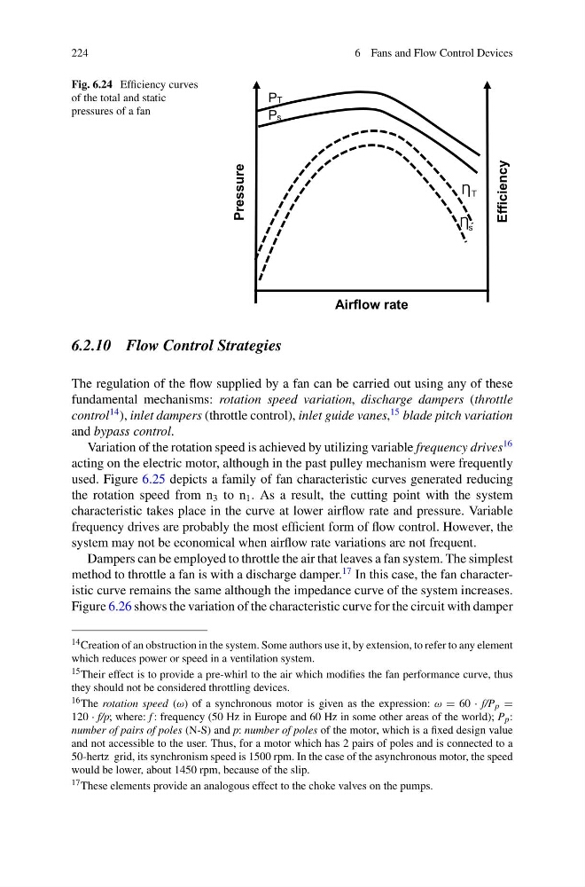
Fig. 6.24 Efficiency curves
of the total and static
pressures of a fan
PT
Pressure
Efficiency
Ps
Airflow rate
T
s
6.2.10 Flow Control Strategies
The regulation of the flow supplied by a fan can be carried out using any of these
fundamental mechanisms: rotation speed variation, discharge dampers (throttle
control
14 ), inlet dampers (throttle control), inlet guide vanes,
15 blade pitch variation
and bypass control.
Variation of the rotation speed is achieved by utilizing variable frequency drives
16
acting on the electric motor, although in the past pulley mechanism were frequently
used. Figure 6.25 depicts a family of fan characteristic curves generated reducing
the rotation speed from n 3 to n 1 . As a result, the cutting point with the system
characteristic takes place in the curve at lower airflow rate and pressure. Variable
frequency drives are probably the most efficient form of flow control. However, the
system may not be economical when airflow rate variations are not frequent.
Dampers can be employed to throttle the air that leaves a fan system. The simplest
method to throttle a fan is with a discharge damper.
17 In this case, the fan characteristic curve remains the same although the impedance curve of the system increases.
Figure 6.26 shows the variation of the characteristic curve for the circuit with damper
14 Creation of an obstruction in the system. Some authors use it, by extension, to refer to any element
which reduces power or speed in a ventilation system.
15 Their effect is to provide a pre-whirl to the air which modifies the fan performance curve, thus
they should not be considered throttling devices.
16 The rotation speed (ω) of a synchronous motor is given as the expression: ω = 60 · f/P p =
120 · f/p; where: f : frequency (50 Hz in Europe and 60 Hz in some other areas of the world); P p :
number of pairs of poles (N-S) and p: number of poles of the motor, which is a fixed design value
and not accessible to the user. Thus, for a motor which has 2 pairs of poles and is connected to a
50-hertz grid, its synchronism speed is 1500 rpm. In the case of the asynchronous motor, the speed
would be lower, about 1450 rpm, because of the slip.
17 These elements provide an analogous effect to the choke valves on the pumps.
6 Fans and Flow Control Devices
Fig. 6.24 Efficiency curves
of the total and static
pressures of a fan
PT
Pressure
Efficiency
Ps
Airflow rate
T
s
6.2.10 Flow Control Strategies
The regulation of the flow supplied by a fan can be carried out using any of these
fundamental mechanisms: rotation speed variation, discharge dampers (throttle
control
14 ), inlet dampers (throttle control), inlet guide vanes,
15 blade pitch variation
and bypass control.
Variation of the rotation speed is achieved by utilizing variable frequency drives
16
acting on the electric motor, although in the past pulley mechanism were frequently
used. Figure 6.25 depicts a family of fan characteristic curves generated reducing
the rotation speed from n 3 to n 1 . As a result, the cutting point with the system
characteristic takes place in the curve at lower airflow rate and pressure. Variable
frequency drives are probably the most efficient form of flow control. However, the
system may not be economical when airflow rate variations are not frequent.
Dampers can be employed to throttle the air that leaves a fan system. The simplest
method to throttle a fan is with a discharge damper.
17 In this case, the fan characteristic curve remains the same although the impedance curve of the system increases.
Figure 6.26 shows the variation of the characteristic curve for the circuit with damper
14 Creation of an obstruction in the system. Some authors use it, by extension, to refer to any element
which reduces power or speed in a ventilation system.
15 Their effect is to provide a pre-whirl to the air which modifies the fan performance curve, thus
they should not be considered throttling devices.
16 The rotation speed (ω) of a synchronous motor is given as the expression: ω = 60 · f/P p =
120 · f/p; where: f : frequency (50 Hz in Europe and 60 Hz in some other areas of the world); P p :
number of pairs of poles (N-S) and p: number of poles of the motor, which is a fixed design value
and not accessible to the user. Thus, for a motor which has 2 pairs of poles and is connected to a
50-hertz grid, its synchronism speed is 1500 rpm. In the case of the asynchronous motor, the speed
would be lower, about 1450 rpm, because of the slip.
17 These elements provide an analogous effect to the choke valves on the pumps.