

6.2 Fans
205
So, solving for R B :
R B = 4.44
N s
2
m 8
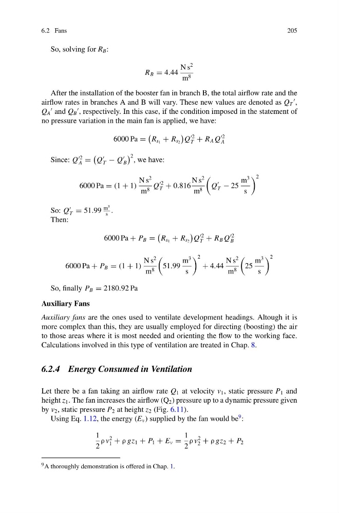
After the installation of the booster fan in branch B, the total airflow rate and the
airflow rates in branches A and B will vary. These new values are denoted as Q T
,
Q A
and Q B
, respectively. In this case, if the condition imposed in the statement of
no pressure variation in the main fan is applied, we have:
6000 Pa =
R s 1 + R s 2
Q
2
T + R A Q
2
A
Since: Q
2
A =
Q
T − Q
B
2 , we have:
6000 Pa = (1 + 1)
N s
2
m 8 Q
2
T + 0.816
N s
2
m 8
Q
T − 25
m
3
s
2
So: Q
T = 51.99
m
3
s
.
Then:
6000 Pa + P B =
R s 1 + R s 2
Q
2
T + R B Q
2
B
6000 Pa + P B = (1 + 1)
N s
2
m 8
51.99
m
3
s
2
+ 4.44
N s
2
m 8
25
m
3
s
2
So, finally P B = 2180.92 Pa
Auxiliary Fans
Auxiliary fans are the ones used to ventilate development headings. Altough it is
more complex than this, they are usually employed for directing (boosting) the air
to those areas where it is most needed and orienting the flow to the working face.
Calculations involved in this type of ventilation are treated in Chap. 8.
6.2.4 Energy Consumed in Ventilation
Let there be a fan taking an airflow rate Q 1 at velocity v 1 , static pressure P 1 and
height z 1 . The fan increases the airflow (Q 2 ) pressure up to a dynamic pressure given
by v 2 , static pressure P 2 at height z 2 (Fig. 6.11).
Using Eq. 1.12, the energy (E v ) supplied by the fan would be
9 :
1
2
ρ v
2
1 + ρ gz 1 + P 1 + E v =
1
2
ρ v
2
2 + ρ gz 2 + P 2
9 A thoroughly demonstration is offered in Chap. 1.
205
So, solving for R B :
R B = 4.44
N s
2
m 8
After the installation of the booster fan in branch B, the total airflow rate and the
airflow rates in branches A and B will vary. These new values are denoted as Q T
,
Q A
and Q B
, respectively. In this case, if the condition imposed in the statement of
no pressure variation in the main fan is applied, we have:
6000 Pa =
R s 1 + R s 2
Q
2
T + R A Q
2
A
Since: Q
2
A =
Q
T − Q
B
2 , we have:
6000 Pa = (1 + 1)
N s
2
m 8 Q
2
T + 0.816
N s
2
m 8
Q
T − 25
m
3
s
2
So: Q
T = 51.99
m
3
s
.
Then:
6000 Pa + P B =
R s 1 + R s 2
Q
2
T + R B Q
2
B
6000 Pa + P B = (1 + 1)
N s
2
m 8
51.99
m
3
s
2
+ 4.44
N s
2
m 8
25
m
3
s
2
So, finally P B = 2180.92 Pa
Auxiliary Fans
Auxiliary fans are the ones used to ventilate development headings. Altough it is
more complex than this, they are usually employed for directing (boosting) the air
to those areas where it is most needed and orienting the flow to the working face.
Calculations involved in this type of ventilation are treated in Chap. 8.
6.2.4 Energy Consumed in Ventilation
Let there be a fan taking an airflow rate Q 1 at velocity v 1 , static pressure P 1 and
height z 1 . The fan increases the airflow (Q 2 ) pressure up to a dynamic pressure given
by v 2 , static pressure P 2 at height z 2 (Fig. 6.11).
Using Eq. 1.12, the energy (E v ) supplied by the fan would be
9 :
1
2
ρ v
2
1 + ρ gz 1 + P 1 + E v =
1
2
ρ v
2
2 + ρ gz 2 + P 2
9 A thoroughly demonstration is offered in Chap. 1.