

4.10 Complex Networks
141
rates are positive if they circulate in this direction and negative if they do so in
the opposite direction.
3. The equivalent resistance of each duct is determined if it is not already known.
These resistances will always have positive values.
4. The pressure drop for each duct is calculated according to i = R i Q
2
i .
5. For the above calculations, the sign of i is lost due to squaring. This can be
remedied by assigning i the same sign as that of the initial value of Q i .
6. The sum of the losses for each mesh is determined with its corresponding sign.
7. The quotient of the loss ( i ) and its corresponding flow rate (Q i ) is calculated.
Note that the sign of this value will always be positive.
8. The sum of the above ratios is determined for each mesh since the system
corrects the calculation on a mesh by mesh basis.
9. Apply the correction formula for each mesh. That is, for each mesh calculate
the quotient according to Eq. 4.27.
10. Apply the correction to the initial flow rate values. This produces new flow rate
values that are used for the following iteration.
11. Repeat until is very small or until the results of successive iterations show
little change.
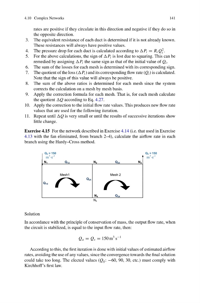
Exercise 4.15 For the network described in Exercise 4.14 (i.e. that used in Exercise
4.13 with the fan eliminated, from branch 2–4), calculate the airflow rate in each
branch using the Hardy–Cross method.
Qa = 150
m
3 s
-1
Qs = 150
m
3 s
-1
N 1
Q 12
N 2
Q 23
N 3
Mesh1
Mesh 2
Q 24
Q 14
N 4
Q 34
N 4
Solution
In accordance with the principle of conservation of mass, the output flow rate, when
the circuit is stabilized, is equal to the input flow rate, then:
Q a = Q s = 150 m
3 s
−1
According to this, the first iteration is done with initial values of estimated airflow
rates, avoiding the use of any values, since the convergence towards the final solution
could take too long. The elected values (Q ij : −60, 90, 30, etc.) must comply with
Kirchhoff’s first law.
141
rates are positive if they circulate in this direction and negative if they do so in
the opposite direction.
3. The equivalent resistance of each duct is determined if it is not already known.
These resistances will always have positive values.
4. The pressure drop for each duct is calculated according to i = R i Q
2
i .
5. For the above calculations, the sign of i is lost due to squaring. This can be
remedied by assigning i the same sign as that of the initial value of Q i .
6. The sum of the losses for each mesh is determined with its corresponding sign.
7. The quotient of the loss ( i ) and its corresponding flow rate (Q i ) is calculated.
Note that the sign of this value will always be positive.
8. The sum of the above ratios is determined for each mesh since the system
corrects the calculation on a mesh by mesh basis.
9. Apply the correction formula for each mesh. That is, for each mesh calculate
the quotient according to Eq. 4.27.
10. Apply the correction to the initial flow rate values. This produces new flow rate
values that are used for the following iteration.
11. Repeat until is very small or until the results of successive iterations show
little change.
Exercise 4.15 For the network described in Exercise 4.14 (i.e. that used in Exercise
4.13 with the fan eliminated, from branch 2–4), calculate the airflow rate in each
branch using the Hardy–Cross method.
Qa = 150
m
3 s
-1
Qs = 150
m
3 s
-1
N 1
Q 12
N 2
Q 23
N 3
Mesh1
Mesh 2
Q 24
Q 14
N 4
Q 34
N 4
Solution
In accordance with the principle of conservation of mass, the output flow rate, when
the circuit is stabilized, is equal to the input flow rate, then:
Q a = Q s = 150 m
3 s
−1
According to this, the first iteration is done with initial values of estimated airflow
rates, avoiding the use of any values, since the convergence towards the final solution
could take too long. The elected values (Q ij : −60, 90, 30, etc.) must comply with
Kirchhoff’s first law.