

4.10 Complex Networks
131
Mesh M 1
Branch
Pressure drop
Fan
N 1 − N 2
0.3 Q 2
12
No
N 2 − N 4
−0.8 · 50 2
+P v
N 1 − N 4
−0.4 (150 − Q 12 ) 2
No
Mesh M 1
H ij = 0
−0.1 Q 2
12 + 120 Q 12 − 11000 + P v = 0
Mesh M 2
Branch
Pressure drop
Fan
N 2 − N 3
−0.1 (Q 12 + 50) 2
No
N 4 − N 3
−0.2 (Q 12 − 100) 2
No
N 4 − N 2
−0.8 · 50 2
+P v
Mesh M 2
H ij = 0
−0.3 Q 2
12 + 30 Q 12 −4.250 + P v = 0
Mesh M 1 :
−0.1 Q
2
12 + 120 Q 12 − 11000 + P v = 0
Mesh M 2 ·(−1): +0.3 Q
2
12 −30 Q 12 + 4250 − P v = 0
-----------------------------------------Adding the expressions for M 1 and M 2 allows us to solve for P v :
M 1 + M 2 : +0.2 Q
2
12 + 90 Q 12 − 6750 = 0
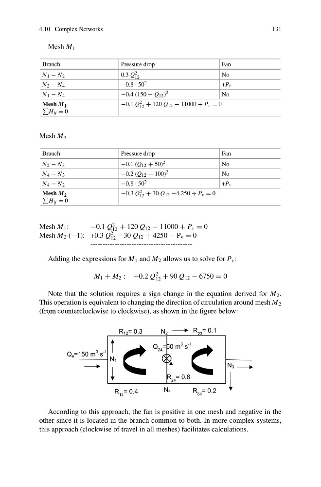
Note that the solution requires a sign change in the equation derived for M 2 .
This operation is equivalent to changing the direction of circulation around mesh M 2
(from counterclockwise to clockwise), as shown in the figure below:
N 1
N 2
N 4
N 3
Q e =150 m
3
⋅s
-1
R 12 = 0.3
R 14 = 0.4
R 23 = 0.1
R 34 = 0.2
R 24 = 0.8
Q 24 =50 m
3
⋅s
-1
According to this approach, the fan is positive in one mesh and negative in the
other since it is located in the branch common to both. In more complex systems,
this approach (clockwise of travel in all meshes) facilitates calculations.
131
Mesh M 1
Branch
Pressure drop
Fan
N 1 − N 2
0.3 Q 2
12
No
N 2 − N 4
−0.8 · 50 2
+P v
N 1 − N 4
−0.4 (150 − Q 12 ) 2
No
Mesh M 1
H ij = 0
−0.1 Q 2
12 + 120 Q 12 − 11000 + P v = 0
Mesh M 2
Branch
Pressure drop
Fan
N 2 − N 3
−0.1 (Q 12 + 50) 2
No
N 4 − N 3
−0.2 (Q 12 − 100) 2
No
N 4 − N 2
−0.8 · 50 2
+P v
Mesh M 2
H ij = 0
−0.3 Q 2
12 + 30 Q 12 −4.250 + P v = 0
Mesh M 1 :
−0.1 Q
2
12 + 120 Q 12 − 11000 + P v = 0
Mesh M 2 ·(−1): +0.3 Q
2
12 −30 Q 12 + 4250 − P v = 0
-----------------------------------------Adding the expressions for M 1 and M 2 allows us to solve for P v :
M 1 + M 2 : +0.2 Q
2
12 + 90 Q 12 − 6750 = 0
Note that the solution requires a sign change in the equation derived for M 2 .
This operation is equivalent to changing the direction of circulation around mesh M 2
(from counterclockwise to clockwise), as shown in the figure below:
N 1
N 2
N 4
N 3
Q e =150 m
3
⋅s
-1
R 12 = 0.3
R 14 = 0.4
R 23 = 0.1
R 34 = 0.2
R 24 = 0.8
Q 24 =50 m
3
⋅s
-1
According to this approach, the fan is positive in one mesh and negative in the
other since it is located in the branch common to both. In more complex systems,
this approach (clockwise of travel in all meshes) facilitates calculations.