

60
2 Basic Components
on a reduced chord between the trailing edge and a point obtained by projection in
the axial direction of the trailing edge of the neighbouring profile [7].
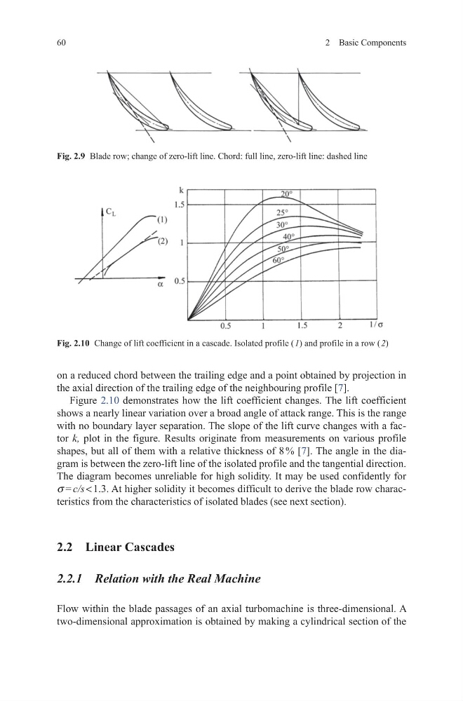
Figure 2.10 demonstrates how the lift coefficient changes. The lift coefficient
shows a nearly linear variation over a broad angle of attack range. This is the range
with no boundary layer separation. The slope of the lift curve changes with a factor k, plot in the figure. Results originate from measurements on various profile
shapes, but all of them with a relative thickness of 8 % [7]. The angle in the diagram is between the zero-lift line of the isolated profile and the tangential direction.
The diagram becomes unreliable for high solidity. It may be used confidently for
s = c/s < 1.3. At higher solidity it becomes difficult to derive the blade row characteristics from the characteristics of isolated blades (see next section).
2.2 Linear Cascades
2.2.1 Relation with the Real Machine
Flow within the blade passages of an axial turbomachine is three-dimensional. A
two-dimensional approximation is obtained by making a cylindrical section of the
Fig. 2.9 Blade row; change of zero-lift line. Chord: full line, zero-lift line: dashed line
Fig. 2.10 Change of lift coefficient in a cascade. Isolated profile ( 1) and profile in a row ( 2)
2 Basic Components
on a reduced chord between the trailing edge and a point obtained by projection in
the axial direction of the trailing edge of the neighbouring profile [7].
Figure 2.10 demonstrates how the lift coefficient changes. The lift coefficient
shows a nearly linear variation over a broad angle of attack range. This is the range
with no boundary layer separation. The slope of the lift curve changes with a factor k, plot in the figure. Results originate from measurements on various profile
shapes, but all of them with a relative thickness of 8 % [7]. The angle in the diagram is between the zero-lift line of the isolated profile and the tangential direction.
The diagram becomes unreliable for high solidity. It may be used confidently for
s = c/s < 1.3. At higher solidity it becomes difficult to derive the blade row characteristics from the characteristics of isolated blades (see next section).
2.2 Linear Cascades
2.2.1 Relation with the Real Machine
Flow within the blade passages of an axial turbomachine is three-dimensional. A
two-dimensional approximation is obtained by making a cylindrical section of the
Fig. 2.9 Blade row; change of zero-lift line. Chord: full line, zero-lift line: dashed line
Fig. 2.10 Change of lift coefficient in a cascade. Isolated profile ( 1) and profile in a row ( 2)