

55
2.1 Aerofoils
This causes, as sketched in Fig. 2.6, the velocity profile to become more concave
as the flow evolves. With a sufficiently large adverse pressure gradient, the velocity close to the profile surface may attain a very low value, causing separation
downstream of this position. With the reasoning with streamtubes following the
surface, as sketched in Fig. 2.6, it cannot be analysed how the transition from
attached flow to separated flow exactly occurs, as the velocity within a streamtube cannot change sign. The reasoning however explains the origin of separation,
which is sufficient here. We conclude that separation may occur in the trailing
edge zone at the suction side, if the adverse pressure gradient is sufficiently large.
We also conclude that separation cannot occur at the pressure side if the flow is
everywhere accelerating. We further notice that a turbulent boundary layer has a
far better resistance to separation than a laminar one. A turbulent boundary layer is
much thicker than a laminar one, but turbulence generation is most intense close to
the wall. With a turbulent boundary layer, the near-wall velocity gradient is much
higher and thus more momentum is present near the wall than within a laminar
boundary layer.
2.1.5 Loss Mechanism Associated to Friction: Energy
Dissipation
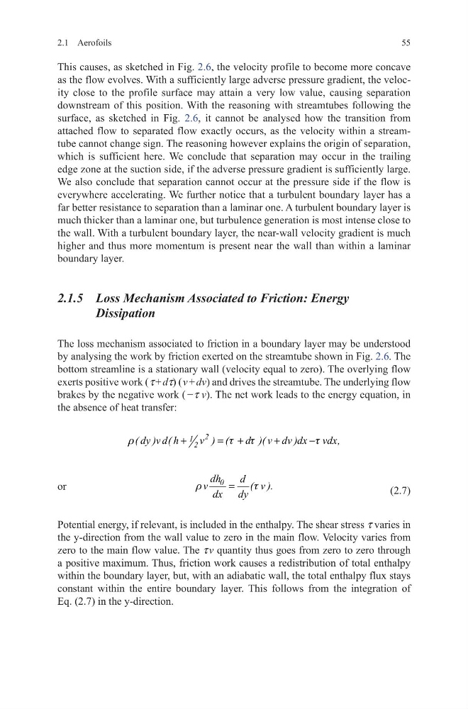
The loss mechanism associated to friction in a boundary layer may be understood
by analysing the work by friction exerted on the streamtube shown in Fig. 2.6. The
bottom streamline is a stationary wall (velocity equal to zero). The overlying flow
exerts positive work ( τ + dτ) ( v + dv) and drives the streamtube. The underlying flow
brakes by the negative work ( −τ v). The net work leads to the energy equation, in
the absence of heat transfer:
or
2
1 2
( dy )v d( h
v ) (
d )( v dv )dx vdx,
r
t
t
t
+
= +
+
−
(2.7)
Potential energy, if relevant, is included in the enthalpy. The shear stress τ varies in
the y-direction from the wall value to zero in the main flow. Velocity varies from
zero to the main flow value. The τ v quantity thus goes from zero to zero through
a positive maximum. Thus, friction work causes a redistribution of total enthalpy
within the boundary layer, but, with an adiabatic wall, the total enthalpy flux stays
constant within the entire boundary layer. This follows from the integration of
Eq. (2.7) in the y-direction.
0
dh
d
v
( v ).
dx dy
r
t
=
2.1 Aerofoils
This causes, as sketched in Fig. 2.6, the velocity profile to become more concave
as the flow evolves. With a sufficiently large adverse pressure gradient, the velocity close to the profile surface may attain a very low value, causing separation
downstream of this position. With the reasoning with streamtubes following the
surface, as sketched in Fig. 2.6, it cannot be analysed how the transition from
attached flow to separated flow exactly occurs, as the velocity within a streamtube cannot change sign. The reasoning however explains the origin of separation,
which is sufficient here. We conclude that separation may occur in the trailing
edge zone at the suction side, if the adverse pressure gradient is sufficiently large.
We also conclude that separation cannot occur at the pressure side if the flow is
everywhere accelerating. We further notice that a turbulent boundary layer has a
far better resistance to separation than a laminar one. A turbulent boundary layer is
much thicker than a laminar one, but turbulence generation is most intense close to
the wall. With a turbulent boundary layer, the near-wall velocity gradient is much
higher and thus more momentum is present near the wall than within a laminar
boundary layer.
2.1.5 Loss Mechanism Associated to Friction: Energy
Dissipation
The loss mechanism associated to friction in a boundary layer may be understood
by analysing the work by friction exerted on the streamtube shown in Fig. 2.6. The
bottom streamline is a stationary wall (velocity equal to zero). The overlying flow
exerts positive work ( τ + dτ) ( v + dv) and drives the streamtube. The underlying flow
brakes by the negative work ( −τ v). The net work leads to the energy equation, in
the absence of heat transfer:
or
2
1 2
( dy )v d( h
v ) (
d )( v dv )dx vdx,
r
t
t
t
+
= +
+
−
(2.7)
Potential energy, if relevant, is included in the enthalpy. The shear stress τ varies in
the y-direction from the wall value to zero in the main flow. Velocity varies from
zero to the main flow value. The τ v quantity thus goes from zero to zero through
a positive maximum. Thus, friction work causes a redistribution of total enthalpy
within the boundary layer, but, with an adiabatic wall, the total enthalpy flux stays
constant within the entire boundary layer. This follows from the integration of
Eq. (2.7) in the y-direction.
0
dh
d
v
( v ).
dx dy
r
t
=