

30
1 Working Principles
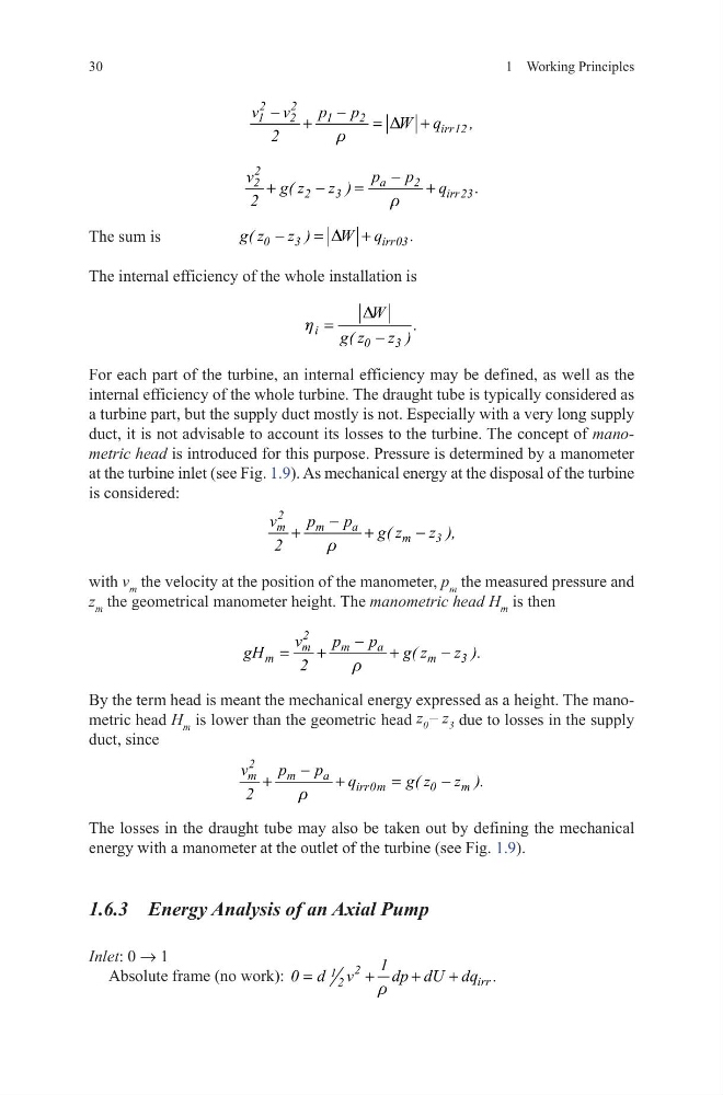
The sum is
0
3
irr03
g( z z )
W q
.
D
−
=
+
The internal efficiency of the whole installation is
For each part of the turbine, an internal efficiency may be defined, as well as the
internal efficiency of the whole turbine. The draught tube is typically considered as
a turbine part, but the supply duct mostly is not. Especially with a very long supply
duct, it is not advisable to account its losses to the turbine. The concept of manometric head is introduced for this purpose. Pressure is determined by a manometer
at the turbine inlet (see Fig. 1.9). As mechanical energy at the disposal of the turbine
is considered:
with v m the velocity at the position of the manometer, p m the measured pressure and
z m the geometrical manometer height. The manometric head H m is then
By the term head is meant the mechanical energy expressed as a height. The manometric head H m is lower than the geometric head z 0 – z 3 due to losses in the supply
duct, since
The losses in the draught tube may also be taken out by defining the mechanical
energy with a manometer at the outlet of the turbine (see Fig. 1.9).
1.6.3 Energy Analysis of an Axial Pump
Inlet: 0 → 1
Absolute frame (no work):
2
1
irr
2
1
0 d v
dp dU dq .
r
=
+
+
+
2
2
1
2
1
2
irr12
v v
p p
W q
,
2
D
r
−
−
+
=
+
2
a
2
2
2
3
irr 23
p
p
v
g( z z )
q
.
2
r
−
+
−
=
+
i
0
3
W
.
g( z z )
D
h =
−
2
m
m
a
m
3
v
p
p
g( z
z ),
2
r
−
+
+
−
2
m
m
a
m
m
3
v
p
p
gH
g( z
z ).
2
r
−
=
+
+
−
2
m
m
a
irr0m
0
m
v
p
p
q
g( z z ).
2
r
−
+
+
=
−
1 Working Principles
The sum is
0
3
irr03
g( z z )
W q
.
D
−
=
+
The internal efficiency of the whole installation is
For each part of the turbine, an internal efficiency may be defined, as well as the
internal efficiency of the whole turbine. The draught tube is typically considered as
a turbine part, but the supply duct mostly is not. Especially with a very long supply
duct, it is not advisable to account its losses to the turbine. The concept of manometric head is introduced for this purpose. Pressure is determined by a manometer
at the turbine inlet (see Fig. 1.9). As mechanical energy at the disposal of the turbine
is considered:
with v m the velocity at the position of the manometer, p m the measured pressure and
z m the geometrical manometer height. The manometric head H m is then
By the term head is meant the mechanical energy expressed as a height. The manometric head H m is lower than the geometric head z 0 – z 3 due to losses in the supply
duct, since
The losses in the draught tube may also be taken out by defining the mechanical
energy with a manometer at the outlet of the turbine (see Fig. 1.9).
1.6.3 Energy Analysis of an Axial Pump
Inlet: 0 → 1
Absolute frame (no work):
2
1
irr
2
1
0 d v
dp dU dq .
r
=
+
+
+
2
2
1
2
1
2
irr12
v v
p p
W q
,
2
D
r
−
−
+
=
+
2
a
2
2
2
3
irr 23
p
p
v
g( z z )
q
.
2
r
−
+
−
=
+
i
0
3
W
.
g( z z )
D
h =
−
2
m
m
a
m
3
v
p
p
g( z
z ),
2
r
−
+
+
−
2
m
m
a
m
m
3
v
p
p
gH
g( z
z ).
2
r
−
=
+
+
−
2
m
m
a
irr0m
0
m
v
p
p
q
g( z z ).
2
r
−
+
+
=
−