

529
14.6 Performance Characteristics
A 1 is the through-flow area and n is the polytropic exponent. The inducer inlet is the
most critical since the further the flow enters the impeller, the lower is the velocity
w and the higher is the enthalpy h. By introducing an average value of the blade
speed at the inlet, we obtain an approximation of the choking mass flow rate. The
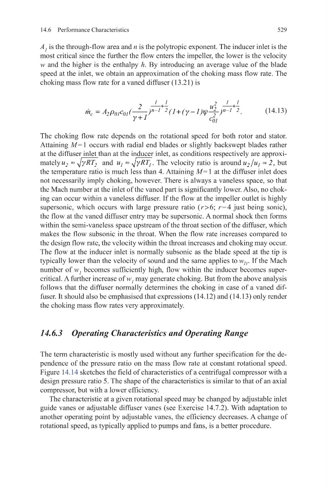
choking mass flow rate for a vaned diffuser (13.21) is
(14.13)
The choking flow rate depends on the rotational speed for both rotor and stator.
Attaining M = 1 occurs with radial end blades or slightly backswept blades rather
at the diffuser inlet than at the inducer inlet, as conditions respectively are approximately
g
≈
2
2
u
RT and
g
≈
1
1
u
RT . The velocity ratio is around
≈
2 1
u u 2, but
the temperature ratio is much less than 4. Attaining M = 1 at the diffuser inlet does
not necessarily imply choking, however. There is always a vaneless space, so that
the Mach number at the inlet of the vaned part is significantly lower. Also, no choking can occur within a vaneless diffuser. If the flow at the impeller outlet is highly
supersonic, which occurs with large pressure ratio ( r > 6; r = 4 just being sonic),
the flow at the vaned diffuser entry may be supersonic. A normal shock then forms
within the semi-vaneless space upstream of the throat section of the diffuser, which
makes the flow subsonic in the throat. When the flow rate increases compared to
the design flow rate, the velocity within the throat increases and choking may occur.
The flow at the inducer inlet is normally subsonic as the blade speed at the tip is
typically lower than the velocity of sound and the same applies to w 1t . If the Mach
number of w 1 becomes sufficiently high, flow within the inducer becomes supercritical. A further increase of w 1 may generate choking. But from the above analysis
follows that the diffuser normally determines the choking in case of a vaned diffuser. It should also be emphasised that expressions (14.12) and (14.13) only render
the choking mass flow rates very approximately.
14.6.3 Operating Characteristics and Operating Range
The term characteristic is mostly used without any further specification for the dependence of the pressure ratio on the mass flow rate at constant rotational speed.
Figure 14.14 sketches the field of characteristics of a centrifugal compressor with a
design pressure ratio 5. The shape of the characteristics is similar to that of an axial
compressor, but with a lower efficiency.
The characteristic at a given rotational speed may be changed by adjustable inlet
guide vanes or adjustable diffuser vanes (see Exercise 14.7.2). With adaptation to
another operating point by adjustable vanes, the efficiency decreases. A change of
rotational speed, as typically applied to pumps and fans, is a better procedure.
r
g
y
g
+
+
−
−
=
+ −
+
1 1
1 1
2
2
n 1 2
n 1 2
c
2 01 01
2
01
u
2
m
A
c (
)
( 1 (
1)
)
.
1
c
14.6 Performance Characteristics
A 1 is the through-flow area and n is the polytropic exponent. The inducer inlet is the
most critical since the further the flow enters the impeller, the lower is the velocity
w and the higher is the enthalpy h. By introducing an average value of the blade
speed at the inlet, we obtain an approximation of the choking mass flow rate. The
choking mass flow rate for a vaned diffuser (13.21) is
(14.13)
The choking flow rate depends on the rotational speed for both rotor and stator.
Attaining M = 1 occurs with radial end blades or slightly backswept blades rather
at the diffuser inlet than at the inducer inlet, as conditions respectively are approximately
g
≈
2
2
u
RT and
g
≈
1
1
u
RT . The velocity ratio is around
≈
2 1
u u 2, but
the temperature ratio is much less than 4. Attaining M = 1 at the diffuser inlet does
not necessarily imply choking, however. There is always a vaneless space, so that
the Mach number at the inlet of the vaned part is significantly lower. Also, no choking can occur within a vaneless diffuser. If the flow at the impeller outlet is highly
supersonic, which occurs with large pressure ratio ( r > 6; r = 4 just being sonic),
the flow at the vaned diffuser entry may be supersonic. A normal shock then forms
within the semi-vaneless space upstream of the throat section of the diffuser, which
makes the flow subsonic in the throat. When the flow rate increases compared to
the design flow rate, the velocity within the throat increases and choking may occur.
The flow at the inducer inlet is normally subsonic as the blade speed at the tip is
typically lower than the velocity of sound and the same applies to w 1t . If the Mach
number of w 1 becomes sufficiently high, flow within the inducer becomes supercritical. A further increase of w 1 may generate choking. But from the above analysis
follows that the diffuser normally determines the choking in case of a vaned diffuser. It should also be emphasised that expressions (14.12) and (14.13) only render
the choking mass flow rates very approximately.
14.6.3 Operating Characteristics and Operating Range
The term characteristic is mostly used without any further specification for the dependence of the pressure ratio on the mass flow rate at constant rotational speed.
Figure 14.14 sketches the field of characteristics of a centrifugal compressor with a
design pressure ratio 5. The shape of the characteristics is similar to that of an axial
compressor, but with a lower efficiency.
The characteristic at a given rotational speed may be changed by adjustable inlet
guide vanes or adjustable diffuser vanes (see Exercise 14.7.2). With adaptation to
another operating point by adjustable vanes, the efficiency decreases. A change of
rotational speed, as typically applied to pumps and fans, is a better procedure.
r
g
y
g
+
+
−
−
=
+ −
+
1 1
1 1
2
2
n 1 2
n 1 2
c
2 01 01
2
01
u
2
m
A
c (
)
( 1 (
1)
)
.
1
c