

519
14.3 Pressure Ratio
Further, a strong deceleration ratio w 2 /w 1 is required to attain the absolute rotor
outlet velocity as tangential as possible. Extreme decelerations are applied with
radial end blades or slightly backswept blades, until w 2 /w 1t ≈ 0.60 (a typical value is
0.65). It is surprising that such strong decelerations can be realised without an extreme form of flow separation. The reason is that very intense secondary flows occur within radial impellers, driving core flow fluid to the boundary layers. Strengthening of the boundary layers within high-deceleration zones may thus be attained
by an appropriate rotor channel design, similar to the optimisation of bent diffusers
with hydraulic turbines. Strong deceleration generates a high non-homogeneity of
the rotor outflow, of course, causing large mixing loss. Backward sweep of the
blades reduces the need for strong deceleration. Complete optimisation is thus very
delicate and requires accurate numerical simulation tools. So, the foregoing derived
optimum inlet diameter (14.3) (with coefficient 1.73) is only very approximate.
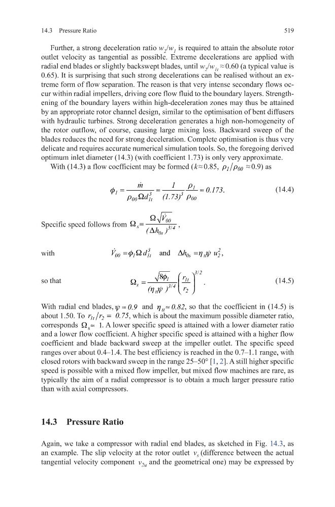
With (14.3) a flow coefficient may be formed ( k ≈ 0.85, r r
1 00 ≈ 0.9) as
(14.4)
Specific speed follows from
/
W
W
D
=
00
s
3 4
0s
V
( h )
,
with
so that
(14.5)
With radial end blades, y ≈ 0.9 and h ≈
tt 0.82, so that the coefficient in (14.5) is
about 1.50. To
=
1t 2
r r
0.75, which is about the maximum possible diameter ratio,
corresponds s 1
W ≈ . A lower specific speed is attained with a lower diameter ratio
and a lower flow coefficient. A higher specific speed is attained with a higher flow
coefficient and blade backward sweep at the impeller outlet. The specific speed
ranges over about 0.4–1.4. The best efficiency is reached in the 0.7–1.1 range, with
closed rotors with backward sweep in the range 25–50° [1, 2]. A still higher specific
speed is possible with a mixed flow impeller, but mixed flow machines are rare, as
typically the aim of a radial compressor is to obtain a much larger pressure ratio
than with axial compressors.
14.3 Pressure Ratio
Again, we take a compressor with radial end blades, as sketched in Fig. 14.3, as
an example. The slip velocity at the rotor outlet v s (difference between the actual
tangential velocity component v 2u and the geometrical one) may be expressed by
.
r
f
r
r W
=
≈
≈
1
1
3
3 00
00
1t
m
1
0.173
d
(1.73)
and
,
3
2
00
1
1t
0s
tt
2
V
d
h
u
f W
D
h y
=
=
/
/
8
.
3 2
1
1t
s
3 4
2
tt
r
r
(
)
f
W
h y
=
14.3 Pressure Ratio
Further, a strong deceleration ratio w 2 /w 1 is required to attain the absolute rotor
outlet velocity as tangential as possible. Extreme decelerations are applied with
radial end blades or slightly backswept blades, until w 2 /w 1t ≈ 0.60 (a typical value is
0.65). It is surprising that such strong decelerations can be realised without an extreme form of flow separation. The reason is that very intense secondary flows occur within radial impellers, driving core flow fluid to the boundary layers. Strengthening of the boundary layers within high-deceleration zones may thus be attained
by an appropriate rotor channel design, similar to the optimisation of bent diffusers
with hydraulic turbines. Strong deceleration generates a high non-homogeneity of
the rotor outflow, of course, causing large mixing loss. Backward sweep of the
blades reduces the need for strong deceleration. Complete optimisation is thus very
delicate and requires accurate numerical simulation tools. So, the foregoing derived
optimum inlet diameter (14.3) (with coefficient 1.73) is only very approximate.
With (14.3) a flow coefficient may be formed ( k ≈ 0.85, r r
1 00 ≈ 0.9) as
(14.4)
Specific speed follows from
/
W
W
D
=
00
s
3 4
0s
V
( h )
,
with
so that
(14.5)
With radial end blades, y ≈ 0.9 and h ≈
tt 0.82, so that the coefficient in (14.5) is
about 1.50. To
=
1t 2
r r
0.75, which is about the maximum possible diameter ratio,
corresponds s 1
W ≈ . A lower specific speed is attained with a lower diameter ratio
and a lower flow coefficient. A higher specific speed is attained with a higher flow
coefficient and blade backward sweep at the impeller outlet. The specific speed
ranges over about 0.4–1.4. The best efficiency is reached in the 0.7–1.1 range, with
closed rotors with backward sweep in the range 25–50° [1, 2]. A still higher specific
speed is possible with a mixed flow impeller, but mixed flow machines are rare, as
typically the aim of a radial compressor is to obtain a much larger pressure ratio
than with axial compressors.
14.3 Pressure Ratio
Again, we take a compressor with radial end blades, as sketched in Fig. 14.3, as
an example. The slip velocity at the rotor outlet v s (difference between the actual
tangential velocity component v 2u and the geometrical one) may be expressed by
.
r
f
r
r W
=
≈
≈
1
1
3
3 00
00
1t
m
1
0.173
d
(1.73)
and
,
3
2
00
1
1t
0s
tt
2
V
d
h
u
f W
D
h y
=
=
/
/
8
.
3 2
1
1t
s
3 4
2
tt
r
r
(
)
f
W
h y
=