

518
14 Radial Compressors
to obtain the lowest possible relative velocity at the impeller outlet, so that the mixing loss at the impeller outlet is minimal. Further, the rotor outlet velocity in the
absolute frame is then as tangential as possible. This minimises the radial dimensions of the diffuser and the volute, which reduces the losses within these elements.
Minimising the Mach number at the inlet also realises the greatest possible margin
against choking, if the rotor inflow is the most critical for choking (see discussion
in Sect. 14.6).
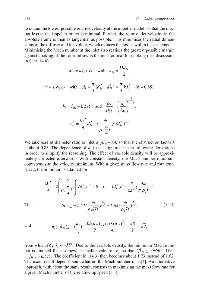
We take here as diameter ratio at inlet d 1h /d 1t = 0.4, so that the obstruction factor k
is about 0.85. The dependence of ρ 1 to v 1 is ignored in the following derivations
in order to simplify the reasoning. The effect of variable density will be approximately corrected afterwards. With constant density, the Mach number minimum
corresponds to the velocity minimum. With a given mass flow rate and rotational
speed, the minimum is attained for
Thus
(14.3)
and
from which
t
1 o
(
)
55
b
≈ − ° . Due to the variable density, the minimum Mach number is attained for a somewhat smaller value of v 1 , so that
1t o
(
)
60
b
≈ − °. Then
.
≈
1 1t
0
v
.577
u
The coefficient in (14.3) then becomes about 1.73 instead of 1.62.
The exact result depends somewhat on the Mach number of v 1 [4]. An alternative
approach, with about the same result, consists in maximising the mass flow rate for
a given Mach number of the relative tip speed [3, 4].
wi
,
th
W
=
=
+
2
2
2
1t
1t
1
1t
1t
d
u
w
v
2
u
with
(
)
(
0.85),
p
p
r
=
=
−
=
≈
2
2
2
1 1 1
1
1t
1h
1t
m
v A
A
d
d
kd
k
4
4
1/2
and
,
1
1
2
1
1
1
01
1
01
01
h
h h
v
h
g
r
r
−
=
−
=
.
4
W
p
r
−
=
+
2
2
2
2 2
2
1t
1t
1t
1
m
w
d
(
) (d )
4
k
.
or
2
2
2
3
2 3
2
1t
1t
2
1
1
m
8
4m
2
(d )
0
(d )
(
)
k
4
k
4
W
p
r
p r
W
−
−
=
=
,
1
1
3
3
1t o
1
1
m
m
(d ) 1.53(
)
1.62(
)
k
r W
r W
≈
≈
( )
( )
(
)
( )
,
2
1t o 1
1t o
1
1t o
1
d
k d
u
8
tg
2
v
2
4m
2
W
r p
b
−
=
=
=
=
14 Radial Compressors
to obtain the lowest possible relative velocity at the impeller outlet, so that the mixing loss at the impeller outlet is minimal. Further, the rotor outlet velocity in the
absolute frame is then as tangential as possible. This minimises the radial dimensions of the diffuser and the volute, which reduces the losses within these elements.
Minimising the Mach number at the inlet also realises the greatest possible margin
against choking, if the rotor inflow is the most critical for choking (see discussion
in Sect. 14.6).
We take here as diameter ratio at inlet d 1h /d 1t = 0.4, so that the obstruction factor k
is about 0.85. The dependence of ρ 1 to v 1 is ignored in the following derivations
in order to simplify the reasoning. The effect of variable density will be approximately corrected afterwards. With constant density, the Mach number minimum
corresponds to the velocity minimum. With a given mass flow rate and rotational
speed, the minimum is attained for
Thus
(14.3)
and
from which
t
1 o
(
)
55
b
≈ − ° . Due to the variable density, the minimum Mach number is attained for a somewhat smaller value of v 1 , so that
1t o
(
)
60
b
≈ − °. Then
.
≈
1 1t
0
v
.577
u
The coefficient in (14.3) then becomes about 1.73 instead of 1.62.
The exact result depends somewhat on the Mach number of v 1 [4]. An alternative
approach, with about the same result, consists in maximising the mass flow rate for
a given Mach number of the relative tip speed [3, 4].
wi
,
th
W
=
=
+
2
2
2
1t
1t
1
1t
1t
d
u
w
v
2
u
with
(
)
(
0.85),
p
p
r
=
=
−
=
≈
2
2
2
1 1 1
1
1t
1h
1t
m
v A
A
d
d
kd
k
4
4
1/2
and
,
1
1
2
1
1
1
01
1
01
01
h
h h
v
h
g
r
r
−
=
−
=
.
4
W
p
r
−
=
+
2
2
2
2 2
2
1t
1t
1t
1
m
w
d
(
) (d )
4
k
.
or
2
2
2
3
2 3
2
1t
1t
2
1
1
m
8
4m
2
(d )
0
(d )
(
)
k
4
k
4
W
p
r
p r
W
−
−
=
=
,
1
1
3
3
1t o
1
1
m
m
(d ) 1.53(
)
1.62(
)
k
r W
r W
≈
≈
( )
( )
(
)
( )
,
2
1t o 1
1t o
1
1t o
1
d
k d
u
8
tg
2
v
2
4m
2
W
r p
b
−
=
=
=
=