

511
14.1 Construction Forms and Applications
filaments. The rotor inlet part resembles an axial compressor. This part is termed an
inducer. Half of the blades are extended into the inducer part, the other half are not.
In other words, there are primary blades and splitter blades. Splitter blades divide
the channel that is formed by primary blades into two parts, from a certain distance
beyond the rotor inlet plane. The reason for the presence of splitter blades will be
discussed later. The figure is also intended to demonstrate that even the primary
blades do not have a very complex shape.
14.1.2 General Shape of a Radial Compressor
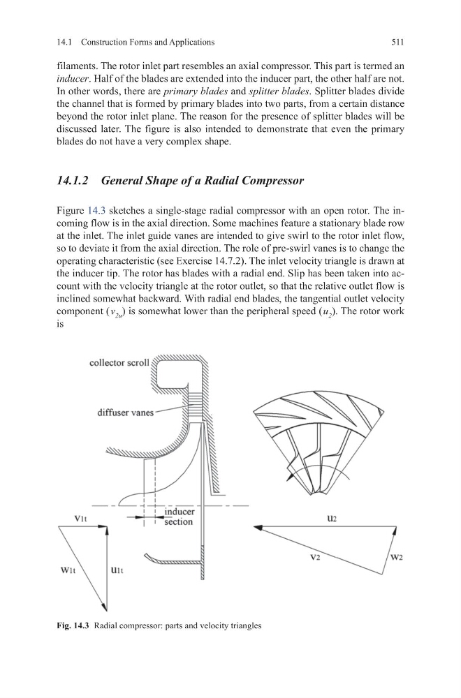
Figure 14.3 sketches a single-stage radial compressor with an open rotor. The incoming flow is in the axial direction. Some machines feature a stationary blade row
at the inlet. The inlet guide vanes are intended to give swirl to the rotor inlet flow,
so to deviate it from the axial direction. The role of pre-swirl vanes is to change the
operating characteristic (see Exercise 14.7.2). The inlet velocity triangle is drawn at
the inducer tip. The rotor has blades with a radial end. Slip has been taken into account with the velocity triangle at the rotor outlet, so that the relative outlet flow is
inclined somewhat backward. With radial end blades, the tangential outlet velocity
component ( v 2u ) is somewhat lower than the peripheral speed ( u 2 ). The rotor work
is
Fig. 14.3 Radial compressor: parts and velocity triangles
14.1 Construction Forms and Applications
filaments. The rotor inlet part resembles an axial compressor. This part is termed an
inducer. Half of the blades are extended into the inducer part, the other half are not.
In other words, there are primary blades and splitter blades. Splitter blades divide
the channel that is formed by primary blades into two parts, from a certain distance
beyond the rotor inlet plane. The reason for the presence of splitter blades will be
discussed later. The figure is also intended to demonstrate that even the primary
blades do not have a very complex shape.
14.1.2 General Shape of a Radial Compressor
Figure 14.3 sketches a single-stage radial compressor with an open rotor. The incoming flow is in the axial direction. Some machines feature a stationary blade row
at the inlet. The inlet guide vanes are intended to give swirl to the rotor inlet flow,
so to deviate it from the axial direction. The role of pre-swirl vanes is to change the
operating characteristic (see Exercise 14.7.2). The inlet velocity triangle is drawn at
the inducer tip. The rotor has blades with a radial end. Slip has been taken into account with the velocity triangle at the rotor outlet, so that the relative outlet flow is
inclined somewhat backward. With radial end blades, the tangential outlet velocity
component ( v 2u ) is somewhat lower than the peripheral speed ( u 2 ). The rotor work
is
Fig. 14.3 Radial compressor: parts and velocity triangles