

510
14 Radial Compressors
typically higher. The tendency to higher values comes from the lower density of the
fluid. Most applications require pressure ratios far above 10. The compressor must
then have multiple stages, which creates the tendency towards rather large work
per stage. The tendency towards large flow factors comes from better efficiency of
screw compressors and reciprocating compressors for low flow rates.
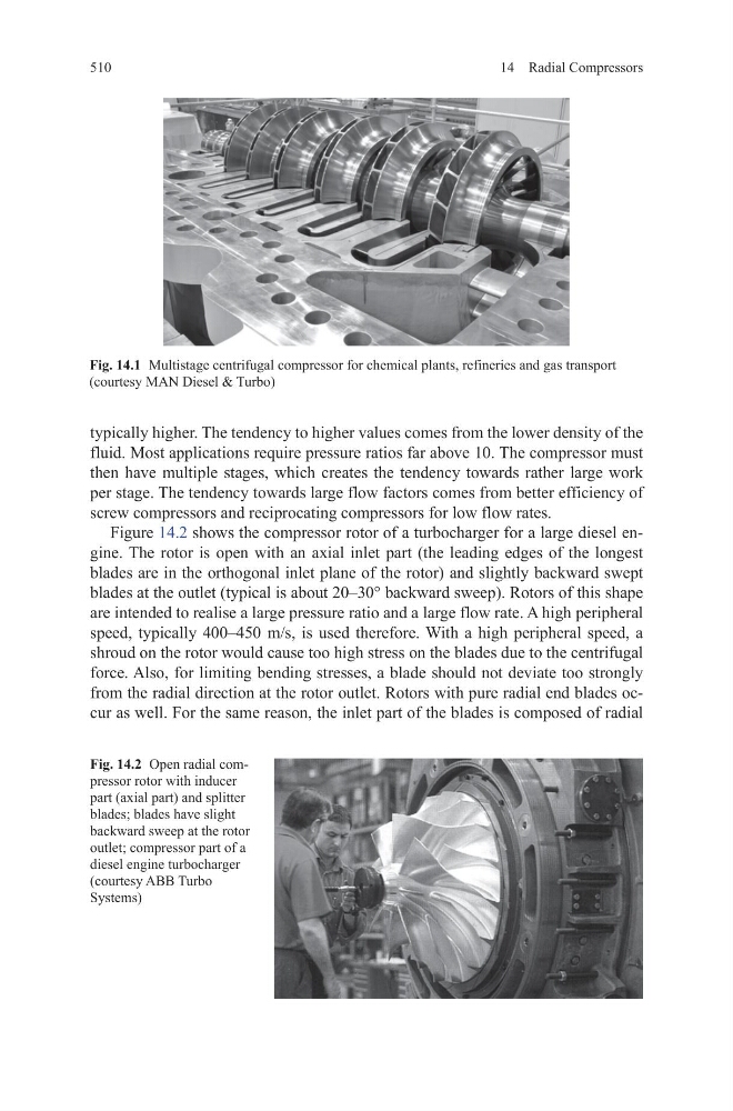
Figure 14.2 shows the compressor rotor of a turbocharger for a large diesel engine. The rotor is open with an axial inlet part (the leading edges of the longest
blades are in the orthogonal inlet plane of the rotor) and slightly backward swept
blades at the outlet (typical is about 20–30° backward sweep). Rotors of this shape
are intended to realise a large pressure ratio and a large flow rate. A high peripheral
speed, typically 400–450 m/s, is used therefore. With a high peripheral speed, a
shroud on the rotor would cause too high stress on the blades due to the centrifugal
force. Also, for limiting bending stresses, a blade should not deviate too strongly
from the radial direction at the rotor outlet. Rotors with pure radial end blades occur as well. For the same reason, the inlet part of the blades is composed of radial
Fig. 14.2 Open radial compressor rotor with inducer
part (axial part) and splitter
blades; blades have slight
backward sweep at the rotor
outlet; compressor part of a
diesel engine turbocharger
(courtesy ABB Turbo
Systems)
Fig. 14.1 Multistage centrifugal compressor for chemical plants, refineries and gas transport
(courtesy MAN Diesel & Turbo)
14 Radial Compressors
typically higher. The tendency to higher values comes from the lower density of the
fluid. Most applications require pressure ratios far above 10. The compressor must
then have multiple stages, which creates the tendency towards rather large work
per stage. The tendency towards large flow factors comes from better efficiency of
screw compressors and reciprocating compressors for low flow rates.
Figure 14.2 shows the compressor rotor of a turbocharger for a large diesel engine. The rotor is open with an axial inlet part (the leading edges of the longest
blades are in the orthogonal inlet plane of the rotor) and slightly backward swept
blades at the outlet (typical is about 20–30° backward sweep). Rotors of this shape
are intended to realise a large pressure ratio and a large flow rate. A high peripheral
speed, typically 400–450 m/s, is used therefore. With a high peripheral speed, a
shroud on the rotor would cause too high stress on the blades due to the centrifugal
force. Also, for limiting bending stresses, a blade should not deviate too strongly
from the radial direction at the rotor outlet. Rotors with pure radial end blades occur as well. For the same reason, the inlet part of the blades is composed of radial
Fig. 14.2 Open radial compressor rotor with inducer
part (axial part) and splitter
blades; blades have slight
backward sweep at the rotor
outlet; compressor part of a
diesel engine turbocharger
(courtesy ABB Turbo
Systems)
Fig. 14.1 Multistage centrifugal compressor for chemical plants, refineries and gas transport
(courtesy MAN Diesel & Turbo)