

495
13.4 Compressor Blade Profiles
the blade passage shock. The oblique shock is very weak, with negligible losses.
The normal shock provides the main part of the compression. This shock is also the
main loss source, not only because of its intrinsic dissipation, but also because of
interaction between the shock and the boundary layer. For preventing separation,
the boundary layer should be turbulent at the impact zone. Optimisation of a transonic cascade is strongly determined by minimising shock losses. Depending on
the Mach number of the oncoming flow, at the suction side in front of the normal
shock, either a slight acceleration is tolerable (convex shape), or no acceleration can
be allowed (plane shape) or even a deceleration must be realised (concave shape).
Downstream of the shock, the flow is subsonic. Within this part of the blade passage, further deceleration combined with flow turning occurs.
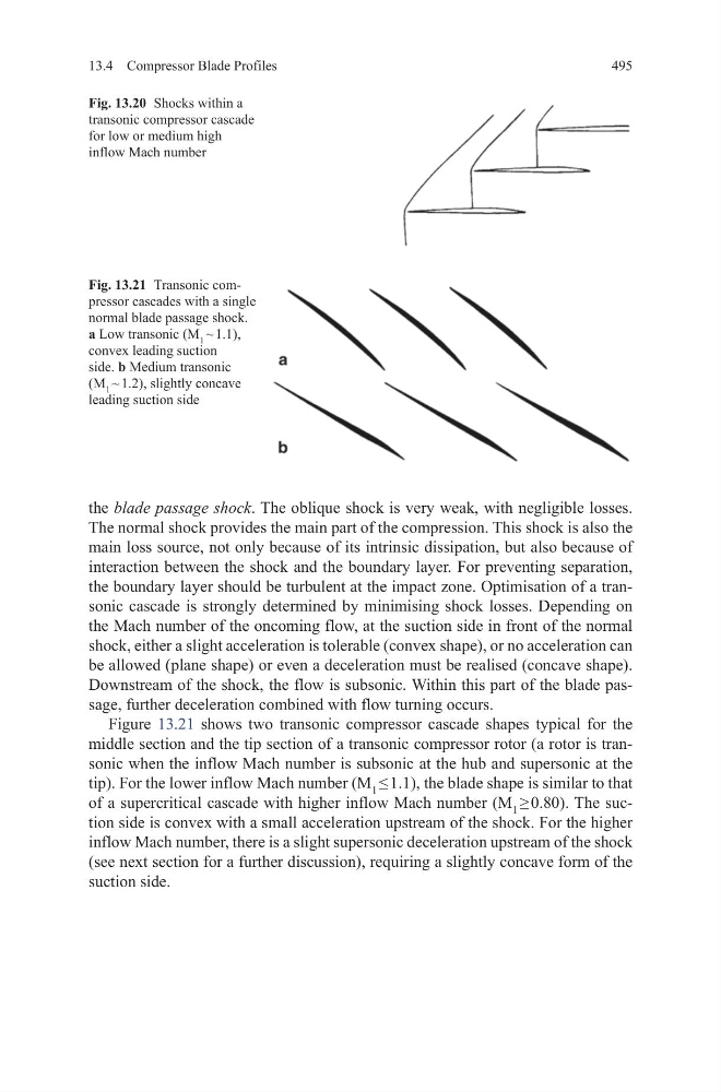
Figure 13.21 shows two transonic compressor cascade shapes typical for the
middle section and the tip section of a transonic compressor rotor (a rotor is transonic when the inflow Mach number is subsonic at the hub and supersonic at the
tip). For the lower inflow Mach number (M 1 ≤ 1.1), the blade shape is similar to that
of a supercritical cascade with higher inflow Mach number (M 1 ≥ 0.80). The suction side is convex with a small acceleration upstream of the shock. For the higher
inflow Mach number, there is a slight supersonic deceleration upstream of the shock
(see next section for a further discussion), requiring a slightly concave form of the
suction side.
Fig. 13.20 Shocks within a
transonic compressor cascade
for low or medium high
inflow Mach number
Fig. 13.21 Transonic compressor cascades with a single
normal blade passage shock.
a Low transonic (M 1 ~ 1.1),
convex leading suction
side. b Medium transonic
(M 1 ~ 1.2), slightly concave
leading suction side
13.4 Compressor Blade Profiles
the blade passage shock. The oblique shock is very weak, with negligible losses.
The normal shock provides the main part of the compression. This shock is also the
main loss source, not only because of its intrinsic dissipation, but also because of
interaction between the shock and the boundary layer. For preventing separation,
the boundary layer should be turbulent at the impact zone. Optimisation of a transonic cascade is strongly determined by minimising shock losses. Depending on
the Mach number of the oncoming flow, at the suction side in front of the normal
shock, either a slight acceleration is tolerable (convex shape), or no acceleration can
be allowed (plane shape) or even a deceleration must be realised (concave shape).
Downstream of the shock, the flow is subsonic. Within this part of the blade passage, further deceleration combined with flow turning occurs.
Figure 13.21 shows two transonic compressor cascade shapes typical for the
middle section and the tip section of a transonic compressor rotor (a rotor is transonic when the inflow Mach number is subsonic at the hub and supersonic at the
tip). For the lower inflow Mach number (M 1 ≤ 1.1), the blade shape is similar to that
of a supercritical cascade with higher inflow Mach number (M 1 ≥ 0.80). The suction side is convex with a small acceleration upstream of the shock. For the higher
inflow Mach number, there is a slight supersonic deceleration upstream of the shock
(see next section for a further discussion), requiring a slightly concave form of the
suction side.
Fig. 13.20 Shocks within a
transonic compressor cascade
for low or medium high
inflow Mach number
Fig. 13.21 Transonic compressor cascades with a single
normal blade passage shock.
a Low transonic (M 1 ~ 1.1),
convex leading suction
side. b Medium transonic
(M 1 ~ 1.2), slightly concave
leading suction side