

490
13 Axial Compressors
The effect of sweep is illustrated in Fig. 13.16 (right). Sweep is called positive
when the leading edge is moved parallel with the chord towards the oncoming flow.
The figure demonstrates positive sweep at the hub and negative sweep at the casing.
A first effect of sweep is exerting torsion on the streamsurfaces. The flow velocity
at the leading edge may be split in a component parallel to the leading edge and a
component perpendicular to it. The parallel component stays nearly unmodified in
the flow over the profile. The perpendicular component increases at the suction side
and decreases at the pressure side. With positive sweep, the streamline at the suction
side moves towards the end wall and the streamline at the pressure side moves away
from the end wall. The torsion on the streamsurface results in a vortex motion counteracting the passage vortex (Fig. 13.10). So, secondary flow reduction requires
combined sweep, positive at the hub and positive at the casing. But reduction of the
secondary flow is not necessarily beneficial, as the secondary vortices move core
flow fluid to boundary layer regions and vice versa. A particular beneficial effect
of the secondary flow is redistribution of energy between core flow and end wall
layers. We note that the vortex induced by positive sweep supplies mass flow from
the central part of a blade to the corner of the suction side and the hub. This supply
decreases the corner stall. This is certainly favourable for loss reduction in the hub
region of a stator. Another favourable effect of sweep is, as with aircraft wings,
Mach number lowering of the flow perpendicular to the leading edge, causing reduction of shock loss with supercritical and transonic profiles. This is favourable
for rotor tip sections.
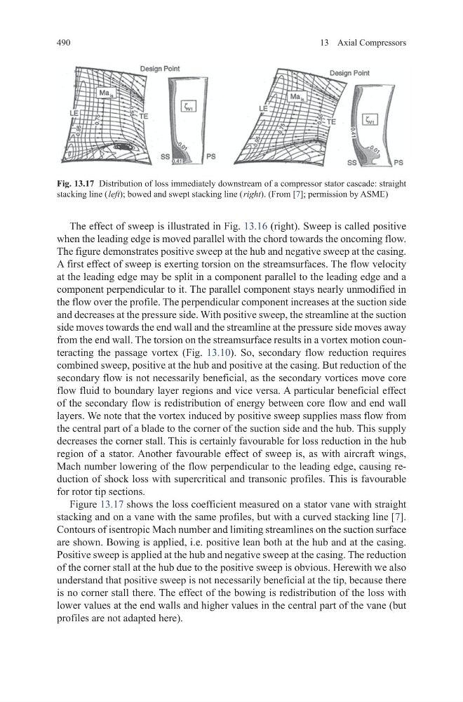
Figure 13.17 shows the loss coefficient measured on a stator vane with straight
stacking and on a vane with the same profiles, but with a curved stacking line [7].
Contours of isentropic Mach number and limiting streamlines on the suction surface
are shown. Bowing is applied, i.e. positive lean both at the hub and at the casing.
Positive sweep is applied at the hub and negative sweep at the casing. The reduction
of the corner stall at the hub due to the positive sweep is obvious. Herewith we also
understand that positive sweep is not necessarily beneficial at the tip, because there
is no corner stall there. The effect of the bowing is redistribution of the loss with
lower values at the end walls and higher values in the central part of the vane (but
profiles are not adapted here).
Fig. 13.17 Distribution of loss immediately downstream of a compressor stator cascade: straight
stacking line ( left); bowed and swept stacking line ( right). (From [7]; permission by ASME)
13 Axial Compressors
The effect of sweep is illustrated in Fig. 13.16 (right). Sweep is called positive
when the leading edge is moved parallel with the chord towards the oncoming flow.
The figure demonstrates positive sweep at the hub and negative sweep at the casing.
A first effect of sweep is exerting torsion on the streamsurfaces. The flow velocity
at the leading edge may be split in a component parallel to the leading edge and a
component perpendicular to it. The parallel component stays nearly unmodified in
the flow over the profile. The perpendicular component increases at the suction side
and decreases at the pressure side. With positive sweep, the streamline at the suction
side moves towards the end wall and the streamline at the pressure side moves away
from the end wall. The torsion on the streamsurface results in a vortex motion counteracting the passage vortex (Fig. 13.10). So, secondary flow reduction requires
combined sweep, positive at the hub and positive at the casing. But reduction of the
secondary flow is not necessarily beneficial, as the secondary vortices move core
flow fluid to boundary layer regions and vice versa. A particular beneficial effect
of the secondary flow is redistribution of energy between core flow and end wall
layers. We note that the vortex induced by positive sweep supplies mass flow from
the central part of a blade to the corner of the suction side and the hub. This supply
decreases the corner stall. This is certainly favourable for loss reduction in the hub
region of a stator. Another favourable effect of sweep is, as with aircraft wings,
Mach number lowering of the flow perpendicular to the leading edge, causing reduction of shock loss with supercritical and transonic profiles. This is favourable
for rotor tip sections.
Figure 13.17 shows the loss coefficient measured on a stator vane with straight
stacking and on a vane with the same profiles, but with a curved stacking line [7].
Contours of isentropic Mach number and limiting streamlines on the suction surface
are shown. Bowing is applied, i.e. positive lean both at the hub and at the casing.
Positive sweep is applied at the hub and negative sweep at the casing. The reduction
of the corner stall at the hub due to the positive sweep is obvious. Herewith we also
understand that positive sweep is not necessarily beneficial at the tip, because there
is no corner stall there. The effect of the bowing is redistribution of the loss with
lower values at the end walls and higher values in the central part of the vane (but
profiles are not adapted here).
Fig. 13.17 Distribution of loss immediately downstream of a compressor stator cascade: straight
stacking line ( left); bowed and swept stacking line ( right). (From [7]; permission by ASME)